The code for this tutorial is available here.
The tutorial is divided into multiple parts:
- Part 1: Create elements, handle undo scope.
- Part 2: Create a dialog to manipulate the functionality.
- Part 3: Store dialog data in preferences.
The end result will work like this:
You can also try if you can solve it in BIMx.
Storing Data in Preferences
Archicad API provides support to store data in several places:
- The preferences file: The data will be linked to the user’s computer, not the database. It means it will be the same regardless the actual plan file the user is working on.
- The Archicad plan file: This method links data to the database itself so it will act like any other BIM data (e.g. it will be uploaded to BIM server).
- Associated to BIM elements: The data will act as a core data of BIM elements (e.g. the element should be reserved to modify this data).
- Stored in library parts: The data will be stored in a special tagged section of the library part, and “travel” with it.
When storing the state of the user interface, storing data in preferences is usually the best choice. It won’t affect the database, or any other users in a teamwork project. Saving to preferences usually takes these steps:
- Serialize your data to a binary blob.
- Write the binary data to preferences.
- Read the binary data from preferences.
- Deserialize binary blob to your data.
Serializing Data
Archicad doesn’t know anything about the Add-On, or its data structure, so an Add-On should pass a binary blob (“black box”) to Archicad. It means that the first step should be to convert your data to and from a binary blob. The good news is that the Archicad API has a pretty good support to achieve this.
Now we will prepare our MazeSettings class to make it serializable to and deserializable from a binary format. To achieve this it should be inherited from the GS::Object class that provides basic functionalities for serialization. We also have to use the DECLARE_CLASS_INFO macro that assigns some version information to the class. It can be very useful if we want to modify the data structure while keeping compatibility with previous versions.
The header file for MazeSettings will look like this:
class MazeSettings : public GS::Object
{
	DECLARE_CLASS_INFO;

public:
	MazeSettings ();
	MazeSettings (UInt32 rowCount, UInt32 columnCount, double cellSize, bool createGroup, bool createSlab);

	virtual	GSErrCode Read (GS::IChannel& ic) override;
	virtual	GSErrCode Write (GS::OChannel& oc) const override;

	UInt32	rowCount;
	UInt32	columnCount;
	double	cellSize;
	bool	createGroup;
	bool	createSlab;
};
We also have to declare version information for that class in its .cpp file. We have to provide a name, a guid, and a class version.
GS::ClassInfo MazeSettings::classInfo (
	"MazeSettings",
	GS::Guid ("B45089A9-B372-460B-B145-80E6EBF107C3"),
	GS::ClassVersion (1, 0)
);
The most important part is the Read and Write functions of the class. These are responsible to serialize and deserialize the data. Both functions get an abstract channel as a parameter, and we just have to use its Read or Write functions. It’s important to use frames before any channel operations, because the frame will serialize version information.
GSErrCode MazeSettings::Read (GS::IChannel& ic)
{
	GS::InputFrame frame (ic, classInfo);
	ic.Read (rowCount);
	ic.Read (columnCount);
	ic.Read (cellSize);
	ic.Read (createGroup);
	ic.Read (createSlab);
	return ic.GetInputStatus ();
}

GSErrCode MazeSettings::Write (GS::OChannel& oc) const
{
	GS::OutputFrame frame (oc, classInfo);
	oc.Write (rowCount);
	oc.Write (columnCount);
	oc.Write (cellSize);
	oc.Write (createGroup);
	oc.Write (createSlab);
	return oc.GetOutputStatus ();
}
Storing Data in Preferences
One last step is needed: we have to convert the data to a binary blob, and vice versa. At the end of the day we will need a pointer that points to binary representation of the class. We can achieve this by using IO::MemoryOChannel and IO::MemoryIChannel.
Writing to preferences can be done by the following code:
static bool WriteMazeSettingsToPreferences (const MazeSettings& mazeSettings)
{
	GSErrCode err = NoError;

	IO::MemoryOChannel outputChannel;
	err = mazeSettings.Write (outputChannel);
	if (err != NoError) {
		return false;
	}

	UInt64 bytes = outputChannel.GetDataSize ();
	const char* data = outputChannel.GetDestination ();

	err = ACAPI_SetPreferences (PreferencesVersion, (GSSize) bytes, data);
	if (err != NoError) {
		return false;
	}

	return true;
}
When we would like to use the data we have to read it from preferences. In this case we have to handle the situation when there are no preferences data at all. If so, we have to use the default settings for the maze.
Preferences reading can be done by the following code:
static bool LoadMazeSettingsFromPreferences (MazeSettings& mazeSettings)
{
	GSErrCode err = NoError;

	Int32 version = 0;
	GSSize bytes = 0;
	err = ACAPI_GetPreferences (&version, &bytes, nullptr);
	if (err != NoError || version == 0 || bytes == 0) {
		return false;
	}

	char* data = new char[bytes];
	err = ACAPI_GetPreferences (&version, &bytes, data);
	if (err != NoError) {
		delete[] data;
		return false;
	}

	MazeSettings tempMazeSettings;
	IO::MemoryIChannel inputChannel (data, bytes);
	err = tempMazeSettings.Read (inputChannel);
	if (err != NoError) {
		delete[] data;
		return false;
	}

	mazeSettings = tempMazeSettings;

	delete[] data;
	return true;
}
Putting All Together
Now we should access preferences data before opening the dialog, and store it when the dialog is closed. We will store it only when the user clicks OK, because usually we don’t want to modify anything on Cancel.
static bool GetMazeSettingsFromDialog (MazeSettings& mazeSettings)
{
	MazeSettings initialMazeSettings (10, 20, 1.0, true, true);
	LoadMazeSettingsFromPreferences (initialMazeSettings);

	MazeSettingsDialog mazeSettingsDialog (initialMazeSettings);
	if (mazeSettingsDialog.Invoke ()) {
		mazeSettings = mazeSettingsDialog.GetMazeSettings ();
		WriteMazeSettingsToPreferences (mazeSettings);
		return true;
	} else {
		return false;
	}
}
Summary
Writing to preferences is relatively easy, because we don’t have to deal with teamwork situations. When it comes to storing data in the plan file itself, things get a bit more complicated but of course there is a solution for this scenario as well.
I hope you enjoyed this tutorial series. If you are interested, here are some links for additional resources:
- Find out more details from Archicad API Reference.
- If you are feeling stuck, you can ask your questions in our Developer Forum.
- For some more tutorials check the Add-On Developer Blog.
- Follow us on Twitter to get the latest news.
Archicad Automation API Basics
The goal of the Automation API is to support workflow automation. A Python wrapper is provided by Graphisoft, but you can use any programming language to access this API.
The communication between Archicad and Python happens via HTTP using JSON messages. The Python package helps to establish the connection and hides the JSON communication layer.
What will You Need?
First, you will have to set up your development environment:
- Archicad – Version 24 or above is required. The demo version is perfectly fine for experimenting with the API.
- Python – For executing Python scripts (version 3.7+).
- archicad Python Package – This official archicad PyPI package helps to establish the connection and send commands to Archicad.
- Development Environment – You can use your preferred Python IDE or even a simple text editor can do the job.
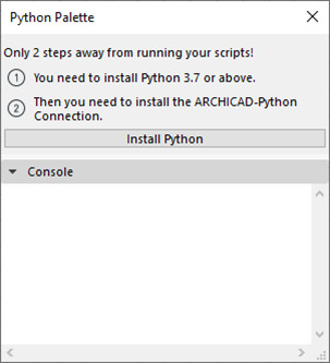
The best way to make sure that your development environment is set up is to open the Python Palette. It warns you if something is missing from your computer and guides you through the installation process. Read further for more details.
Structure of the archicad Python Package
ACConnection is the main class in archicad Python Package. That class represents a live connection to an existing Archicad instance. The most important parts of the class are the followings:
- connect: Use this static method to acquire an ACConnection instance. It automatically finds the running Archicad instance.
- commands: Collection of the available commands for the currently attached Archicad instance. The collection may vary by Archicad versions.
- types: Types required for the API.
- utilities: Utility functions to simplify the usage of the API.
Let’s write your first Python script
Your very first Python script for Archicad will print the number of walls in the currently opened project.
The first part is for the connection, you can use that as a template for your Python scripts for Archicad. The last two lines implement the simple logic of this tutorial script.
Save it as a text file with .py extension.
from archicad import ACConnection

conn = ACConnection.connect()
assert conn

acc = conn.commands
act = conn.types
acu = conn.utilities

walls = acc.GetElementsByType('Wall')

print(f'Number of Walls: {len(walls)}')
How to run Python scripts
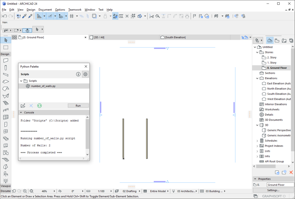
The Python Palette
For beginners the embedded Python Palette inside Archicad helps to run Python scripts. At first you have to switch on the Python Palette feature inside your Work Environment, to do this navigate to the Options/Work Environment/More Options menu. You will find the Python Palette inside the Window/Palettes menu.

Simply browse a folder and the palette will list the runnable scripts inside. By double clicking a script in the list or pushing Run button the selected script will be executed. You can check the output of the script at the Console field of the Python Palette.
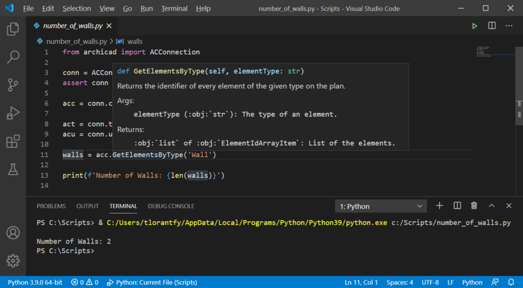
Running script without the Python Palette
The professional Python developers can run their scripts from command line or by using their preferred IDE.
We recommend to use Visual Studio Code with Python Extension. It’s free and runs on both platforms. The built-in IntelliSense supports many useful code editing features including code completion and showing the documentation of the Archicad Automation API commands. Debugging is also pretty straightforward in Visual Studio Code.

Resources
This tutorial covered only the basics, but there are much more.
- Download and try our sample Python scripts.
- Find out the details from Archicad JSON Interface.
- If you are feeling stuck, you can ask your questions at our API Support Portal or in the Developer Forum.
- For some more tutorials check the Add-On Developer Blog.
- Follow us on Twitter to get the latest news.
The code for this tutorial is available here.
The tutorial is divided into multiple parts:
- Part 1: Create elements, handle undo scope.
- Part 2: Create a dialog to manipulate the functionality.
- Part 3: Store dialog data in preferences.
The end result will look something like this:

The Maze Generation Algorithm
At the end of the day the Add-On will generate a random maze. We won’t discuss the details of the maze generation, but you can browse the code, and read about the algorithm on Wikipedia. The maze is generated by Prim’s randomized algorithm.
First Steps
To set up your development environment, please read Getting started with Archicad Add-Ons, and follow the steps you find there. For this tutorial you can download the source code from this link. Please note that the example Add-On works only with the DEMO version of Archicad.
Creating BIM Elements
The maze generator algorithm will generate a bunch of coordinates where we should place the walls. We will also create a slab under the walls.
Units
In the Archicad code everything is stored in meters, so this is the case for Add-Ons as well. It means that every API function will return and expect values in meter, square meter or cubic meter.
On the other hand, users can define units inside Archicad, so if you show a measured value to the user, you have to convert meter to working unit, calculation unit or dimension unit. For user interface it’s a very easy task, because Archicad’s own dialog framework handles unit conversion automatically.
Undo Scope
Every modification in Archicad should be done within an undo scope. It means that the modifications will generate undo steps, and all modifications that fall within one undo scope will be undone in one step. If you try to modify anything without an open undo scope you will get an error from the API call.
The example below shows you how to open an undo scope. You can also specify a string that appears in the Edit menu to show the users what will be undone (“Undo Create wall”).
ACAPI_CallUndoableCommand ("Create wall", [&] () -> GSErrCode {
	// Do some modifications
	return NoError;
});
In case of errors you can return APIERR_CANCEL from the lambda function. In this case all of the modifications in the current undo scope will cancelled.
Creating Elements
To create an element in Archicad you have to define a lot of parameters. Usually you don’t want to define all of them one by one, just use the default values. In Archicad there are default settings for every element. You can set the default settings by clicking on the tool icon without a selected element instance.
These settings are also available via the Archicad API, so you can use them for every parameter you don’t want to specify. Element creation is generally done in three steps:
- Retrieve the element type’s default settings with the
ACAPI_Element_GetDefaultsfunction. - Modify some of the settings of the element by modifying the
API_Elementstructure. - Add geometrical information, and create the element with the modified settings using the
ACAPI_Element_Createfunction.
Creating a Wall
The example below accesses the wall element’s default settings, modifies its start position, end position and reference line location, and places a new wall.
static GSErrCode CreateWallElement (double begX, double begY, double endX, double endY)
{
	GSErrCode err = NoError;

	API_Element wallElement = {};
	wallElement.header.typeID = API_WallID;
	err = ACAPI_Element_GetDefaults (&wallElement, nullptr);
	if (err != NoError) {
		return err;
	}

	wallElement.wall.begC = { begX, begY };
	wallElement.wall.endC = { endX, endY };
	wallElement.wall.referenceLineLocation = APIWallRefLine_Center;
	err = ACAPI_Element_Create (&wallElement, nullptr);
	if (err != NoError) {
		return err;
	}

	return NoError;
}
Creating a Slab
Creating a slab is a bit trickier, because it’s a polygon based element. It means that we have to define the polygon of the slab. To achieve this we will use the element memo concept. The API_ElementMemo structure can contain dynamic data for the element. Polygon is a dynamic data set because it can have any number of vertices, so this is why it’s stored in the memo.
We have to do the following things to create a polygonal element:
- Set the number of polygon vertices in the
API_Elementstructure. Please note that for closed polygons the first and last vertex should be the same. So if you want to create a polygon with 4 edges, than the number of vertices should be 5. - Set the number of sub-polygons in the
API_Elementstructure. This is useful when you want to have holes in the polygon. If the polygon doesn’t contain any holes then the number of sub-polygons should be 1. - Set the coordinates in the
API_ElementMemostructure. You have to allocate an array for the coordinates. The indexing starts from 1, so you have to allocate space for an extra vertex. - Set the sub-polygon end indices in the
API_ElementMemostructure. The indexing starts from 1, so you have to allocate space for an extra index.
You can see all of the above steps altogether here:
static GSErrCode CreateSlabElement (double begX, double begY, double endX, double endY)
{
	GSErrCode err = NoError;

	API_Element slabElement = {};
	slabElement.header.typeID = API_SlabID;
	err = ACAPI_Element_GetDefaults (&slabElement, nullptr);
	if (err != NoError) {
		return err;
	}

	slabElement.slab.poly.nCoords = 5;
	slabElement.slab.poly.nSubPolys = 1;

	API_ElementMemo	slabMemo = {};

	slabMemo.coords = (API_Coord**) BMhAllClear ((slabElement.slab.poly.nCoords + 1) * sizeof (API_Coord));
	(*slabMemo.coords)[1] = { begX, begY };
	(*slabMemo.coords)[2] = { endX, begY };
	(*slabMemo.coords)[3] = { endX, endY };
	(*slabMemo.coords)[4] = { begX, endY };
	(*slabMemo.coords)[5] = (*slabMemo.coords)[1];

	slabMemo.pends = (Int32**) BMhAllClear ((slabElement.slab.poly.nSubPolys + 1) * sizeof (Int32));
	(*slabMemo.pends)[1] = slabElement.slab.poly.nCoords;

	err = ACAPI_Element_Create (&slabElement, &slabMemo);
	ACAPI_DisposeElemMemoHdls (&slabMemo);
	if (err != NoError) {
		return err;
	}

	return NoError;
}
Please note that after using memos you always have to call the ACAPI_DisposeElemMemoHdls function to release the allocated memory.
Putting All Together
The final element creation code in an undo scope should look something like this:
static void GenerateMaze ()
{
	static const int MazeRowCount = 10;
	static const int MazeColCount = 20;
	static const double MazeCellSize = 2.0;
	static const double SlabPadding = 2.0;

	std::vector<MG::WallGeometry> mazeWalls;
	GenerateMazeWallGeometries (MazeRowCount, MazeColCount, MazeCellSize, mazeWalls);

	double slabBegX = -SlabPadding;
	double slabBegY = -SlabPadding;
	double slabEndX = MazeCellSize * MazeColCount + SlabPadding;
	double slabEndY = MazeCellSize * MazeRowCount + SlabPadding;

	GS::UniString undoString = RSGetIndString (AddOnStringsID, UndoStringID, ACAPI_GetOwnResModule ());
	ACAPI_CallUndoableCommand (undoString, [&] () -> GSErrCode {
		GSErrCode err = NoError;
		for (const MG::WallGeometry& mazeWall : mazeWalls) {
			err = CreateWallElement (mazeWall.begX, mazeWall.begY, mazeWall.endX, mazeWall.endY);
			if (err != NoError) {
				return APIERR_CANCEL;
			}
		}
		err = CreateSlabElement (slabBegX, slabBegY, slabEndX, slabEndY);
		if (err != NoError) {
			return APIERR_CANCEL;
		}
		return NoError;
	});
}
Please note that the undo string comes from a resource. String resources can be accessed with the RSGetIndString function.
Summary
This tutorial explained the basics of BIM element creation via the Archicad API.
You can find more resources here:
- Find out more details from Archicad API Reference.
- If you are feeling stuck, you can ask your questions in our Developer Forum.
- For some more tutorials check the Add-On Developer Blog.
- Follow us on Twitter to get the latest news.
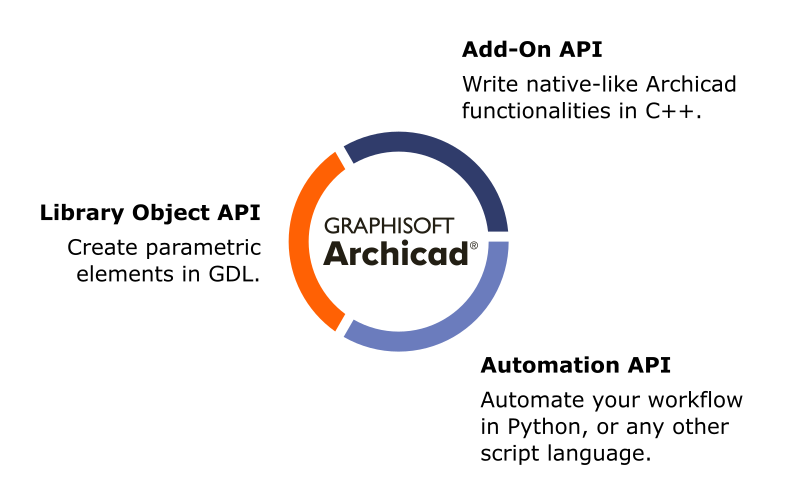
Add-On API (C++)
The Add-On API is the ultimate tool to extend Archicad. You can access almost everything in Archicad and there is a wide range of possibilities to create new functionalities or automate your workflow. Of course, you need to be an experienced developer to use this one. More information…
Automation API (JSON/Python):
The goal of the Automation API is to support workflow automation. A Python wrapper is provided by Graphisoft, but you can use any programming language to access this API. At the moment it focuses on documentation automation. More information…
Library Object API (GDL)
GDL is invented to create fully parametric objects inside Archicad. You can create furniture, doors, windows and much more. GDL is a very powerful technology, there are a lot of possibilites. You need to know some programming to use this technology, but it’s not as hard as C++. More information…
Grasshopper Connection
The Archicad-Grasshopper Connection is the main tool to support generative design by creating real BIM elements in Archicad. The goal here is to create elements and set their parameters based on some rules without any programming knowledge. More information…
PARAM-O
The goal of PARAM-O is to create parametric Archicad objects without scripting. It utilizes the node-based method to create objects, and the end result is a fully functional GDL object. It means that everything you can do in PARAM-O is also possible in GDL, but with PARAM-O you don’t have to write a single line of GDL code. More information…
]]>The code for this tutorial is available here.
The tutorial is divided into multiple parts:
- Part 1: Create elements, handle undo scope.
- Part 2: Create a dialog to manipulate the functionality.
- Part 3: Store dialog data in preferences.
The final dialog will look like this:

Dialog Framework (DG)
To create user interface in Archicad it is highly recommended to use Archicad’s own Dialog framework (DG). It has several advantages:
- Platform Independent: You have to write your code only once, and it will work on Windows and macOS platforms without any modification.
- Handles working units: All of the DG dialogs handle working unit settings, so your dialog will work for people from all around the world.
- Fits in Archicad: All dialogs in Archicad are written with DG, so they will provide a native-like user experience for Archicad users. You don’t have to care about formatting, they will just look beautiful.
Creating a New Dialog
Let’s see how to create a new modal dialog in Archicad. Basically it takes takes three steps:
- Define the resource for the dialog.
- Write the code for the dialog.
- Open the dialog, and use the results.
Define the Resource for the Dialog
The first step is to define the resource for the dialog. You can do it by using Archicad’s internal resource format: grc. This is a platform independent format for describing strings, dialogs, icons and other resources.
Our dialog’s resource will look like this:
'GDLG' ID_ADDON_DLG Modal          40   40  250  452  "Maze Settings" {
/* [  1] */ Button                150  419   90   23    LargePlain  "OK"
/* [  2] */ Button                 50  419   90   23    LargePlain  "Cancel"
/* [  3] */ Icon                   15   10  220  160    10002
/* [  4] */ LeftText               10  180  230   23    LargeBold vCenter "Grid Settings"
/* [  5] */ LeftText               10  210  130   23    LargePlain vCenter "Number of Rows"
/* [  6] */ PosIntEdit            150  210   90   23    LargePlain "1" "50"
/* [  7] */ LeftText               10  240  130   23    LargePlain vCenter "Number of Columns"
/* [  8] */ PosIntEdit            150  240   90   23    LargePlain "1" "50"
/* [  9] */ LeftText               10  270  130   23    LargePlain vCenter "Cell Dimension"
/* [ 10] */ LengthEdit            150  270   90   23    LargePlain "1.00" "50.0"
/* [ 11] */ Separator              10  305  230    2
/* [ 12] */ LeftText               10  317  230   23    LargeBold vCenter "Options"
/* [ 13] */ CheckBox               10  347  230   23    LargePlain "Group placed elements"
/* [ 14] */ CheckBox               10  372  230   23    LargePlain "Place slab under walls"
/* [ 15] */ Separator              10  407  230    2
}
It looks a bit scary at first, but its structure is pretty straightforward.
The first line tells the compiler that it defines a dialog resource (GDLG) for a modal dialog. It also specifies the position, the dimensions and the title of the dialog. After that every line defines a control. All of them specifies the position (top left corner), dimensions (width and height) and some control-dependent properties.
Here are some interesting parts:
- If the dialog has OK and Cancel buttons, they always have to be the first two items, so the default behavior for pressing enter and escape key works automatically when the dialog is open.
- For
Iconcontrols you have to specify the ID of the icon. It usually refers to aGICNresource in another, language-independent resource file. LeftTextis simply a plain static text control with left-aligned text.- The
PosIntEditcontrol can accept only integers, and the minimum and maximum value can be specified as well. LengthEditis used to display a value referring to length. It is highly recommended to use this control when you work with length values, because it automatically handles unit conversion. The minimum and maximum value can be specified here, too.
For dialog resources there is always a connected resource, and it’s the help resource (DLGH). The goal of the help resource is to define help anchors for the dialog. These help anchors are not used by Add-Ons at the moment, but they can also define the tooltip text for every control. In the example below every tooltip text is empty.
'DLGH' ID_ADDON_DLG DLG_Maze_Settings {
1  ""  Button_0
2  ""  Button_1
3  ""  Icon_0
4  ""  LeftText_0
5  ""  LeftText_1
6  ""  PosIntEdit_0
7  ""  LeftText_2
8  ""  PosIntEdit_1
9  ""  LeftText_3
10 ""  LengthEdit_0
11 ""  Separator_0
12 ""  LeftText_4
13 ""  CheckBox_0
14 ""  CheckBox_1
15 ""  Separator_1
}
The Observer Pattern
The dialog framework uses the observer pattern. It means that observer classes can attach to event source classes, and they will get a notification in case of certain events. It’s possible to write dialog and observer classes separately, but in this tutorial we will do it in one class.
Write the Code for the Dialog
The first step is to create a structure to store everything that can be set via the dialog. The MazeSettings class will store the row and column count and the size of maze cells. We also define two options: one is to group all of the elements, and the other is to place a slab under the elements.
class MazeSettings : public GS::Object
{

public:
	MazeSettings (UInt32 rowCount, UInt32 columnCount, double cellSize, bool createGroup, bool createSlab);
	~MazeSettings ();

	UInt32	rowCount;
	UInt32	columnCount;
	double	cellSize;
	bool	createGroup;
	bool	createSlab;
};
The next step is to write a class for the dialog. The dialog class will get the initial settings in the constructor, and it has only one public function that returns the new settings based on user input. The dialog class should be inherited from several classes:
ModalDialog: It defines some functionalities needed for a modal dialog.PanelObserver: It means that our dialog wants to respond to some panel events.ButtonItemObserver: Same as above, our dialog wants to respond to some button events (specifically: pressing the OK or the Cancel button).CompoundItemObserver: It’s a utility class to make it easy to attach all observers with one line.
It also defines some private class members for each control in the dialog, and of course it stores the current settings.
class MazeSettingsDialog :  public DG::ModalDialog,
                            public DG::PanelObserver,
                            public DG::ButtonItemObserver,
                            public DG::CompoundItemObserver
{
public:
    MazeSettingsDialog (const MazeSettings& mazeSettings);
    ~MazeSettingsDialog ();

    const MazeSettings& GetMazeSettings () const;

private:
    virtual void    PanelOpened (const DG::PanelOpenEvent& ev) override;
    virtual void    PanelCloseRequested (const DG::PanelCloseRequestEvent& ev, bool* accepted) override;
    virtual void    ButtonClicked (const DG::ButtonClickEvent& ev) override;

    DG::Button      okButton;
    DG::Button      cancelButton;
    DG::PosIntEdit  rowEdit;
    DG::PosIntEdit  columnEdit;
    DG::LengthEdit  cellSizeEdit;
    DG::CheckBox    groupElementsCheck;
    DG::CheckBox    placeSlabCheck;

    MazeSettings    mazeSettings;
};
Let’s see how it works. The constructor intializes all of the controls with their ids, stores the initial settings, and it attaches the class as an observer to certain event sources. The destructor detaches the class from event sources.
MazeSettingsDialog::MazeSettingsDialog (const MazeSettings& mazeSettings) :
	DG::ModalDialog (ACAPI_GetOwnResModule (), MazeDialogResourceId, ACAPI_GetOwnResModule ()),
	okButton (GetReference (), OKButtonId),
	cancelButton (GetReference (), CancelButtonId),
	rowEdit (GetReference (), RowEditId),
	columnEdit (GetReference (), ColumnEditId),
	cellSizeEdit (GetReference (), CellSizeEditId),
	groupElementsCheck (GetReference (), GroupElementsCheckId),
	placeSlabCheck (GetReference (), PlaceSlabCheckId),
	mazeSettings (mazeSettings)
{
	AttachToAllItems (*this);
	Attach (*this);
}

MazeSettingsDialog::~MazeSettingsDialog ()
{
	Detach (*this);
	DetachFromAllItems (*this);
}
When the dialog is fully initialized, the PanelOpened function will be called. This is the place to initialize controls. In this example the function sets every settings value into the corresponding dialog control.
void MazeSettingsDialog::PanelOpened (const DG::PanelOpenEvent&)
{
	rowEdit.SetValue (mazeSettings.rowCount);
	columnEdit.SetValue (mazeSettings.columnCount);
	cellSizeEdit.SetValue (mazeSettings.cellSize);
	groupElementsCheck.SetState (mazeSettings.createGroup);
	placeSlabCheck.SetState (mazeSettings.createSlab);
}
When the user clicks on a button, the ButtonClicked function will be executed. After clicking on the OK or the Cancel button, it will request to close the dialog with different return codes.
void MazeSettingsDialog::ButtonClicked (const DG::ButtonClickEvent& ev)
{
	if (ev.GetSource () == &okButton) {
		PostCloseRequest (DG::ModalDialog::Accept);
	} else if (ev.GetSource () == &cancelButton) {
		PostCloseRequest (DG::ModalDialog::Cancel);
	}
}
Before the dialog closes, the PanelCloseRequested function will be called. This is a good place to modify settings values based on the controls. We only have to do this if the event is accepted (the user clicked on OK).
void MazeSettingsDialog::PanelCloseRequested (const DG::PanelCloseRequestEvent& ev, bool*)
{
	if (ev.IsAccepted ()) {
		mazeSettings.rowCount = rowEdit.GetValue ();
		mazeSettings.columnCount = columnEdit.GetValue ();
		mazeSettings.cellSize = cellSizeEdit.GetValue ();
		mazeSettings.createGroup = groupElementsCheck.IsChecked ();
		mazeSettings.createSlab = placeSlabCheck.IsChecked ();
	}
}
Open the Dialog
Now we have all the code for the dialog so we can use it. Opening a modal dialog is very simple. We just have to create an instance, call the Invoke method, and check if the user clicked OK or Cancel.
The function below opens the dialog, and stores the settings in an output parameter. If the dialog is closed by pressing OK it will return true, otherwise it will return false. It also defines the initial settings for the dialog so it will be filled with valid values after it is opened.
static bool GetMazeSettingsFromDialog (MazeSettings& mazeSettings)
{
	MazeSettings initialMazeSettings (10, 20, 1.0, true, true);
	MazeSettingsDialog mazeSettingsDialog (initialMazeSettings);
	if (mazeSettingsDialog.Invoke ()) {
		mazeSettings = mazeSettingsDialog.GetMazeSettings ();
		return true;
	} else {
		return false;
	}
}
Summary
This was only the top of the iceberg. Dialog creation has much more possibilities, like creating resizable, dockable palettes, extend existing dialogs and a lot more. You can find more details in the documentation that comes with the API Development Kit.
You can find more resources here:
- Find out more details from Archicad API Reference.
- If you are feeling stuck, you can ask your questions in our Developer Forum.
- For some more tutorials check the Add-On Developer Blog.
- Follow us on Twitter to get the latest news.
Archicad Add-On Basics
The programming language of Archicad Add-Ons is C++, so you have to be familiar with this language to start. Archicad is extensible in several ways: creating new menu commands and dialogs, import-export functionalities, etc. The API itself is general purpose, so you can write various Add-Ons with the same Development Kit.
What will You Need?
First, you will have to set up your development environment:
- Archicad – The demo version is perfectly fine for experimenting with the API, but it has some restrictions that you may experience during the development process.
- API Development Kit – This will allow you to build Archicad Add-Ons on your computer.
- CMake – To generate IDE projects (3.16 minimum version is needed).
- Python – For some build tools (version 2.7+ or 3.8+).
- Depending on your platform you will need a development environment. On Windows this is Microsoft Visual Studio, on MacOS this is Xcode.
For different Archicad versions you will have to use different versions of developer environments. You can see the details in the table below.
| Windows | MacOS | |
|---|---|---|
| Archicad 23 | Visual Studio 2017 (v141 toolset) | Latest Xcode (deployment target macOS 10.12) |
| Archicad 24 | Visual Studio 2017 (v141 toolset) | Latest Xcode (deployment target macOS 10.13) |
| Archicad 25 | Visual Studio 2019 (v142 toolset) | Latest Xcode (deployment target macOS 10.15) |
Structure of the API Development Kit
After you installed the Development Kit you will find three folders at the install location.
- Documentation: This is the folder for API documentation. You can find here a reference for all of the API functions. The documentation is available online, too.
- Examples: Here you can find a lot of example Add-Ons. These can be a good starting point to understand how the API works. Feel free to open the IDE projects, and investigate the possibilities.
- Support: This is the most important folder. It contains all the header and library files for Add-On development, and the tools for resource compilation. This is the folder you will need to build your Add-On.
Let’s Build Your First Add-On
You can start with one of the example Add-Ons, but it’s much easier to start with the template available on GitHub. Download the Archicad Add-On template from here.
Generate IDE Project for the Add-On
After you downloaded the template Add-On, you have to use CMake to generate the project for your favourite Development Environment. Starting from the root folder you can generate the projects with the commands below. Make sure to replace the value of AC_API_DEVKIT_DIR variable with your DevKit installation folder.
On Windows:
mkdir Build
cd Build
cmake -G "Visual Studio 15 2017" -A "x64" -DAC_API_DEVKIT_DIR="C:\API Development Kit 24.3009" ..
cd ..
On MacOS
mkdir Build
cd Build
cmake -G "Xcode" -DAC_API_DEVKIT_DIR=/Applications/GRAPHISOFT\ ARCHICAD\ API\ DevKit\ 24.3009 ..
cd ..
Please note the “..” at the end of the commands. It means that CMake will search for the CMakeLists.txt file in the parent folder.
Build the Add-On
After you generated the IDE project, open it, and press Build. If everything goes fine, you will see no errors or warnings, and an .apx file (Windows) / .bundle (macOS) is created in your result folder.
Try the Add-On in Archicad
You have several ways to load the Add-On in Archicad. For development purposes the best if you browse it directly from your build folder, so every modification will appear in Archicad immediately.
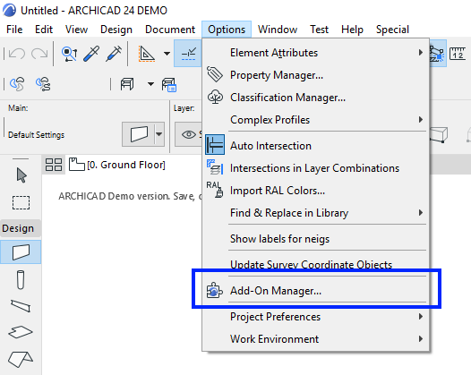
1. Open the Add-On Manager Dialog by selecting Options / Add-On Manager.
2. Click the Add button under the EDIT LIST OF AVAILABLE ADD-ONS tabpage.

3. Browse your Add-On’s .apx/.bundle file, and if everything went well your Add-On will appear in the list of Add-Ons.

4. After closing the Add-On Manager you will see a new command registered by the Add-On: Options / Example AddOn Command.
5. Click on the command, and you will see a very simple dialog created by the Add-On.
Congratulations! You just built your first Archicad Add-On.
Something doesn’t work?
Sometimes you may meet the error messages below. It means that an error happened during the Add-On loading process. There could be several reasons for this issue, see below.
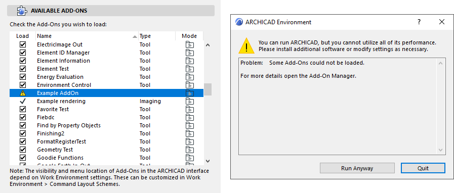
Invalid Development Kit Version
Archicad can’t load an Add-On if it was created with a different version of the Development Kit. Double check the version of your Archicad and the used Development Kit, they should match.
Invalid MDID
Please note, that the example Add-On works only with the DEMO version of Archicad. To release your Add-On you have to register for an MDID (see the details in the Releasing Add-Ons chapter). To work around this issue you can start Archicad in DEMO mode by passing a command line parameter to the executable.
On Windows
Archicad.exe -DEMO
On Mac
"ARCHICAD 24.app/Contents/MacOS/ARCHICAD" -demo
Anatomy of an Add-On
You can find several subfolders in the Sources folder.
Add-On Sources
The source code for the Add-On is in the AddOn folder.
There are four important entry points for Add-Ons.
- CheckEnvironment: This function is called before any other functions. You can check if your Add-On can or allowed to run in the current environment. You also have to provide the Add-On’s name and description. This information will appear in the Add-On Manager.
- RegisterInterface: This function is responsible to register interface elements in Archicad (like menu commands, tool box items, etc.).
- Initialize: This function is called when the Add-On is loaded into the memory, before performing any of the Add-On’s functions.
- FreeData: This function is called when the Add-On is unloaded from the memory.
You can find a more detailed explanation of these functions here.
API_AddonType __ACDLL_CALL CheckEnvironment (API_EnvirParams* envir)
{
    RSGetIndString (&envir->addOnInfo.name, ID_ADDON_INFO, 1, ACAPI_GetOwnResModule ());
    RSGetIndString (&envir->addOnInfo.description, ID_ADDON_INFO, 2, ACAPI_GetOwnResModule ());

    return APIAddon_Normal;
}

GSErrCode __ACDLL_CALL RegisterInterface (void)
{
    return ACAPI_Register_Menu (ID_ADDON_MENU, 0, MenuCode_Tools, MenuFlag_Default);
}

GSErrCode __ACENV_CALL Initialize (void)
{
    return ACAPI_Install_MenuHandler (ID_ADDON_MENU, MenuCommandHandler);
}

GSErrCode __ACENV_CALL FreeData (void)
{
    return NoError;
}
Add-On Resources
The source code for resources is in the AddOnResources folder.
- RFIX: Fix, non-localized resources, like images.
- RFIX.mac, RFIX.win: Platform dependent utility codes.
- RINT: Resources to be localized.
- Tools: Resource builder tool.
Archicad Add-Ons can work on both Windows and macOS platforms, so you can’t use native resource files for localized strings and dialogs. This is why we invented the .grc format, which is a platform independent resource description format working on both platforms. It means that you have to define your resources only once, and then the code will work on both platforms without any modifications.
Debugging
Debugging is pretty straightforward. You just have to attach your debugger to the running Archicad process, and then you can debug your Add-On like any other applications. To make the process more smooth, you can set Archicad as the executable for the Add-On project, and just hit debug to start Archicad.
Visual Studio Tips
Make sure that when you attach to the Archicad process, “Native code” is selected in the “Attach to” item in the dialog. Also note, that the breakpoints doesn’t seem to be active until your Add-On is loaded into the memory. Just place your breakpoints, call one of the Add-On’s functionalities, and it should work.
Call an API Function
Let’s write an example Add-On that counts the number of walls in the current plan.
First of all, you have to include a new header file, because some of it’s functionalities will be needed.
#include "StringConversion.hpp"As you see in the example Add-On you can register a menu command, and then handle it like in the example below. When the user clicks on the command, the code will call the CountNumberOfWalls function to do the job for us.
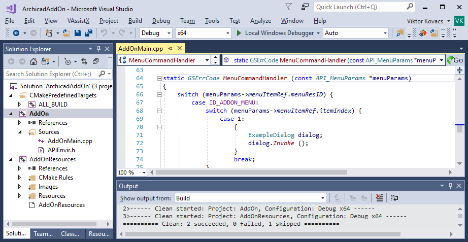
static GSErrCode MenuCommandHandler (const API_MenuParams *menuParams)
{
    switch (menuParams->menuItemRef.menuResID) {
        case ID_ADDON_MENU:
            switch (menuParams->menuItemRef.itemIndex) {
                case 1:
                    CountNumberOfWalls ();
                    break;
            }
            break;
    }
    return NoError;
}
The CountNumberOfWalls function can be implemented like in the example below.
static void CountNumberOfWalls ()
{
    GS::Array<API_Guid> wallGuids;
    GSErrCode err = ACAPI_Element_GetElemList (API_WallID, &wallGuids);
    if (err != NoError) {
        return;
    }

    USize wallCount = wallGuids.GetSize ();
    DG::InformationAlert (GS::ValueToUniString (wallCount), "", "OK");
}
It accesses the list of walls from the current plan, and shows the length of the array in a dialog.
If everything is ok, you should see something like this:

Releasing Add-Ons
To release your Add-On and make it work with all Archicad versions, you have to register as an Archicad developer, and get an MDID for your Add-On. MDID is a unique identifier which identifies the Add-On. Please note that Archicad can’t load two different Add-Ons with the same MDID, so you have to set up different MDIDs for each of your Add-Ons.
Here you can find detailed instructions on registering an MDID.
Resources
This tutorial covered only the basics, but there are much more.
- Find out the details from Archicad API Reference.
- If you are feeling stuck, you can ask your questions in our Developer Forum.
- For some more tutorials check the Add-On Developer Blog.
- Follow us on Twitter to get the latest news.
With this solution you can easily generate IDE projects for Archicad Add-Ons, so you can work in your favorite environment. CMake supports Visual Studio and XCode projects, or you may use Visual Studio Code for development.
You can find detailed instructions on the link below. Please let us know if you have any questions or recommendations.
You can access the CMake template on GitHub:
https://github.com/GRAPHISOFT/archicad-addon-cmake
'MDID' with a resource ID of 32500. This resource defines the unique ID of the add-on.The
'MDID' is composed from two parts:
- Developer ID: the ID of the developer, given by GRAPHISOFT after a successfull registration.
- Local ID: the ID of the add-on, generated by the developer after creating a new add-on at the profile settings.

If your add-on has invalid 'MDID', then ARCHICAD will refuse to load it. If two add-ons have identical 'MDID' resources, then in order to avoid collisions ARCHICAD will refuse to load those. So make sure you generated new identifiers for all of your add-ons!
As it does not require localization, the 'MDID' resource should be contained by the Fix.grc.
Simply copy the two identifiers (highlighted on the picture above) into the grc file:
'MDID' 32500 "Add-On Identifier" {
    628121456
    719857724
}
If you have any further questions, do not hesitate to ask them at [email protected]!
]]>ls -lA@ [you_add-on].bundle). This informs the operating the system that the downloaded file may contain malicious code, and so the operating system tries to verify the identity of the developer to ensure the user’s safety. If that verification fails for some reason then Archicad won’t be able to load your add-on, even though Archicad 23 is set to load non-codesigned add-ons without complaining. Your users will see a dialog similar to this:

So, if you want to distribute your add-on in its pure form (i.e. a compressed .bundle) on macOS, then you’ll have to codesign and notarize your add-ons to make them work correctly on Catalina. It is also advisable to complete the process for add-ons for earlier Archicad versions as well.
You’ll have to perform a similar process if you ship installers or any accompanying tool or application
Here’s how to do it:
- Enroll in the Apple Developer program (yes, the paid one, see this forum thread)
- Set up the App Manager role for a developer (or add a special account with a separate email address)

3. Get your code signing identities for Developer ID: Application & Mac Developer
The easiest way to do that is to add your developer account in Xcode / Preferences / Accounts.
(I guess most of you have already done this, so I don’t go into any detail here)
4. Prepare for notarization
Note that you don’t have to enable the hardened runtime, because it is not required for add-ons, and it’s not easy to setup the proper entitlements anyway.
More details from Apple:
Customizing the Notarization Workflow
5. Install at least Xcode 10
6. Set up your keychain via Terminal
security add-generic-password -a 'AC_USERNAME' -w 'AC_secret_pass' -s 'AC_PASSWORD_HOLDER’
where:AC_USERNAME is the email of the identity to be used for notarization (AC == AppStore Connect)AC_secret_pass is that account’s passwordAC_PASSWORD_HOLDER is a keychain which stores this info.
7. Set up code signing in your project:

8. Build a release version of your add-on (it’ll be code signed automatically)
9. Add a new Aggregate target to the project, name it to ‘[your_add-on] notarized’

10. Place the enclosed notarize.sh script beside your .xcodeproj file
11. Add the following custom build settings to this target (replace ‘com.graphisoft.notarizationtest23‘ with your own bundle identifier):
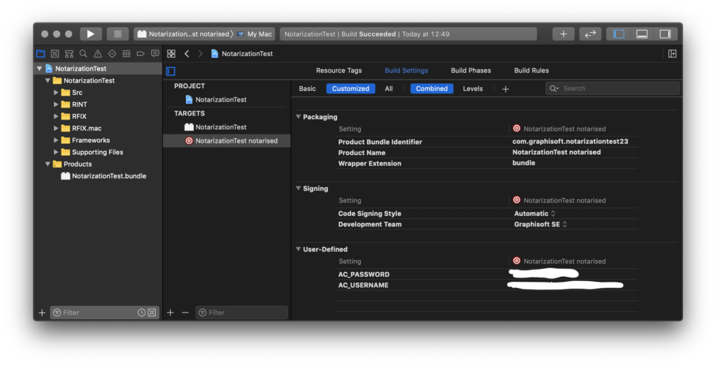
12. Add a new Run Script build phase, and call the downloaded notarize.sh script

if [[ "$CONFIGURATION" = "Release" ]]; then
  "$PROJECT_DIR"/notarize.sh
fi
13. Set the Build Configuration to ‘Release’ for this aggregate scheme

14. Select this new aggregate scheme, and build it, it will send the add-on to Apple for notarization.
Please note that the process takes some time, so wait for the feedback from Apple. If all is well this will notarize the add-on bundle in place.
You can also check if the process was successful:
codesign --test-requirement="=notarized" --verify -vvv --deep [full_path_to_your_add-on.bundle]
After this you can compress and send out the add-on bundle for distribution.
]]>
This blog post demonstrates how to use this new Browser control and how to estabilish connection with ARCHICAD from JavaScript.
I implemented a new Add-On named “Browser Control Test” with a palette (dockable modeless dialog) in ARCHICAD which will load an HTML file. Therefore this post is also a good example for “how to implement a modeless dialog in ARCHICAD”.
I encourage you to download it, build it and test it in ARCHICAD 23!
Preparations
I had to implement a new Add-On named “Browser Control Test”.
The first step of implementing a new Add-On is building up the skeleton structure of the Add-On. I created the Browser_Control folder inside the installed DevKit’s Examples folder and set up the common Add-On folder structure.

RFIX folder
RFIX folder contains the non-localizable platform independent resources (for example images). A GRC file must contain the descriptors of these non-localizable resources, so I created a text file (with UTF-8 with BOM encoding) Browser_ControlFix.grc into the RFIX folder.
Each Add-On must have a unique identifier called MDID, since it does not require localization, my Fix.grc will contain this 'MDID' resource. I generated a new identifier at my profile and copied the generated ids to this GRC file.

The GRC file will be processed by GRAPHISOFT Resource Converter tool (ResConv).
'MDID' 32500 "Add-On Identifier" {
    628121456
    719857724
}
RINT folder
RINT folder contains the localizable resources (for example strings and dialogs). I created the Browser_Control.grc into this folder with the following content:
'STR#' 32000: The string resource with 32000 identifier contains the main information of the Add-On: name and short description. It will be used byCheckEnvironmentfunction and these string will appear inside the Add-On Manager dialog in ARCHICAD to show information about my Add-On.'STR#' 32500: The string resource with 32500 id defines a new menu system. The Add-On registers a new main menu named “Test” with a submenu named “Browser Control” containing a single menu item “Selection Handler Palette”.
In ARCHICAD this menu system will look like the following way:
'GDLG' 32500: Dialog description of the dockable palette with a browser control. See the description below.
'STR#' 32000 "Add-on Name and Description" {
/* [  1] */		"Browser Control Test"
/* [  2] */		"Browser Control Example"
}

'STR#' 32500 "Strings for the Menu" {
/* [   ] */		"Test"
/* [   ] */		"Browser Control"
/* [  1] */			"Selection Handler Palette^ES^EE^EI^ED^EW^E3^EL"
}

'GDLG'  32500    Palette | topCaption | close | grow   0   0  450  150  "Selection Handler"  {
/* [  1] */ Browser			0   0  450  150
}

'DLGH'  32500  DLG_32500_Browser_Palette {
1	"Browser Control"		Browser_0
}
‘GDLG’ dialog descriptor
'GDLG' resource defines a dialog. The Palette keyword after the identifier of the 'GDLG' resource means that it will be a palette, a dockable modeless dialog in ARCHICAD. topCaption keyword is trivial, close keyword means the dialog will have a close button in the corner and grow keyword results that the dialog will be resizable both horizontally and vertically. The keywords are followed by four numbers, which describe the position and size parameters (X, Y, Width, Heigh). In case of a resizable dialog these width and height parameters determines the minimum size of the dialog. Finally, before the braces the title of the dialog can be given.
Between the braces the controls of the dialog are listed. I want only one control on my dialog, a Browser control and it will completely fill my dialog, so it’s position is (0, 0) and it’s size is equal to the dialog’s size.'DLGH' is the help resource for the dialog. It contains prompt messages for the items of the dialog.
RFIX.win folder
RFIX.win folder is for the Windows platform specific resources. This folder contains only the Browser_Control.rc2 file. The .rc2 will be processed by Windows system’s resource compiler tool. This file joins the separeted GRC resource files by including their compilation results, the .grc.rc2 files:
RFIX.mac folder
RFIX.mac folder is for the macOS platform specific resources. This folder must contain an Info.plist file (which will be placed into the built bundle) and the compileGRCs.pl script. That script helps to compile the resource files and creates Localizable.strings file into the bundle. The Xcode project file will execute this script.
Src folder
Src folder contains the C/C++ source code.
In this case the Main.cpp contains the 4 required functions of the Add-On (CheckEnvironment, RegisterInterface, Initialize, FreeData). It registers a menu, and tries to show/hide the dialog when the registered menu was selected.
GSErrCode __ACENV_CALL MenuCommandHandler (const API_MenuParams *menuParams)
{
	switch (menuParams->menuItemRef.menuResID) {
		case BrowserPaletteMenuResId:
			switch (menuParams->menuItemRef.itemIndex) {
				case BrowserPaletteMenuItemIndex:
					ShowOrHideBrowserPalette ();
					break;
			}
			break;
	}

	return NoError;
}

API_AddonType	__ACDLL_CALL	CheckEnvironment (API_EnvirParams* envir)
{
	RSGetIndString (&envir->addOnInfo.name, 32000, 1, ACAPI_GetOwnResModule ());
	RSGetIndString (&envir->addOnInfo.description, 32000, 2, ACAPI_GetOwnResModule ());

	return APIAddon_Preload;
}

GSErrCode	__ACDLL_CALL	RegisterInterface (void)
{
	GSErrCode err = ACAPI_Register_Menu (BrowserPaletteMenuResId, 0, MenuCode_UserDef, MenuFlag_Default);
	if (DBERROR (err != NoError))
		return err;

	return err;
}

GSErrCode __ACENV_CALL	Initialize (void)
{
	GSErrCode err = ACAPI_Install_MenuHandler (BrowserPaletteMenuResId, MenuCommandHandler);
	if (DBERROR (err != NoError))
		return err;

	err = ACAPI_Notify_CatchSelectionChange (BrowserPalette::SelectionChangeHandler);
	if (DBERROR (err != NoError))
		return err;

	err = BrowserPalette::RegisterPaletteControlCallBack ();
	if (DBERROR (err != NoError))
		return err;

	return err;
}

GSErrCode __ACENV_CALL	FreeData (void)
{
	return NoError;
}
How to implement a modeless dialog in ARCHICAD
BrowserPalette class implements a dockable modeless dialog (called palette in ARCHICAD). It’s a good example for a modeless dialog, feel free to reuse this code anytime if you want to implement one!
The BrowserPalette class is derived from the DG::Palette class and in the constructor it defines an own unique GUID for itself and pairs the dialog with the 'GDLG' resource. All modeless dialog must be registered in ARCHICAD to allow ARCHICAD to show/hide/disable/enable the dialog when it’s necessary (for example if you closed ARCHICAD with opened palette, then ARCHICAD will reopen your palette automatically when you restart ARCHICAD with the last profile), use ACAPI_RegisterModelessWindow function for this registration.
The logic behind the dialog
My plan is to implement a palette in ARCHICAD which lists the following information of the selected elements: GUID, type, element ID string. In addition it allows to remove specific elements from the selection and to add element identified by it’s GUID to the selection.
The constructor of the BrowserPalette class calls InitBrowserControl function. Beside initializing the starting page of the browser this function registers the ACAPI JavaScript object and updates the selection info on the page by executing UpdateSelectedElements JavaScript function, which is defined in the HTML code.
static const char*	siteURL = "http://home.sch.bme.hu/~lorantfyt/Selection_Test.html";
static const GS::Guid	paletteGuid ("{FEE27B6B-3873-4834-98B5-F0081AA4CD45}");

BrowserPalette::BrowserPalette () :
	DG::Palette (ACAPI_GetOwnResModule (), BrowserPaletteResId, ACAPI_GetOwnResModule (), paletteGuid),
	browser (GetReference (), BrowserId)
{
	Attach (*this);
	BeginEventProcessing ();
	InitBrowserControl ();
}

BrowserPalette::~BrowserPalette ()
{
	EndEventProcessing ();
}

void BrowserPalette::InitBrowserControl ()
{
	browser.LoadURL (siteURL);
	RegisterACAPIJavaScriptObject ();
	UpdateSelectedElementsOnHTML ();
}

void BrowserPalette::UpdateSelectedElementsOnHTML ()
{
	browser.ExecuteJS ("UpdateSelectedElements ()");
}
Upon startup this example loads the Selection_Test.html HTML page (the downloadable package contains the HTML file also). That HTML file defines an empty table and that table will be populated with the retrieved information of the selected elements from ARCHICAD using JavaScript by calling ACAPI.GetSelectedElements function.
<html>
<head>
	<title>Selection Test</title>

	<script type="text/javascript">
		function UpdateSelectedElements () {
			ACAPI.GetSelectedElements ().then (function (elemInfos) {
				...
				// populate the list with the selection info
				var index, len;
				for (index = 0, len = elemInfos.length; index < len; ++index) {
					...
					removeButton.onclick = function (e) {
						ACAPI.RemoveElementFromSelection (e.currentTarget.guid).then (function (res) {
						});
					};
					...
				}
				...
			});
		}

		function AddElementToSelection () {
			var elemGuidToAddInput = document.getElementById ('elemGuidToAdd');

			ACAPI.AddElementToSelection (elemGuidToAddInput.value).then (function (res) {
				elemGuidToAddInput.value = '';
			});
		}
	</script>
</head>
<body align="center">
	...
	<form>
		<input type="text" id="elemGuidToAdd" size="40">
		<input type="button" onclick="AddElementToSelection ()" value="+">
	</form>
	...
</body>
</html>
The ACAPI JavaScript object is registered from the C++ code and 3 functions were added to it (GetSelectedElements, AddElementToSelection, RemoveElementFromSelection). The given C++ lambda expressions (C++11 feature) define C++ callback functions, those will be executed when the JavaScript code calls the registered function.
void  BrowserPalette::RegisterACAPIJavaScriptObject ()
{
	DG::JSObject* jsACAPI = new DG::JSObject ("ACAPI");

	jsACAPI->AddItem (new DG::JSFunction ("GetSelectedElements", [] (GS::Ref<DG::JSBase>) {
		return ConvertToJavaScriptVariable (GetSelectedElements ());
	}));

	jsACAPI->AddItem (new DG::JSFunction ("AddElementToSelection", [] (GS::Ref<DG::JSBase> param) {
		ModifySelection (GetStringFromJavaScriptVariable (param), AddToSelection);
		return ConvertToJavaScriptVariable (true);
	}));

	jsACAPI->AddItem (new DG::JSFunction ("RemoveElementFromSelection", [] (GS::Ref<DG::JSBase> param) {
		ModifySelection (GetStringFromJavaScriptVariable (param), RemoveFromSelection);
		return ConvertToJavaScriptVariable (true);
	}));

	browser.RegisterAsynchJSObject (jsACAPI);
}
The SelectionChangeHandler function collects the information of the selected elements, since it was registered by ACAPI_Notify_CatchSelectionChange it will be called when the selection in ARCHICAD changes.
The callback associated to GetSelectedElements JavaScript function returns the collected information converted to a JavaScript array object.
GS::Array<BrowserPalette::ElementInfo> BrowserPalette::GetSelectedElements ()
{
	API_SelectionInfo	selectionInfo;
	GS::Array<API_Neig>	selNeigs;
	ACAPI_Selection_Get (&selectionInfo, &selNeigs, false, false);
	BMKillHandle ((GSHandle*)&selectionInfo.marquee.coords);

	GS::Array<BrowserPalette::ElementInfo> selectedElements;
	for (const API_Neig& neig : selNeigs) {
		API_Elem_Head elemHead = {};
		elemHead.guid = neig.guid;
		ACAPI_Element_GetHeader (&elemHead);

		ElementInfo elemInfo;
		elemInfo.guidStr = APIGuidToString (elemHead.guid);
		ACAPI_Goodies (APIAny_GetElemTypeNameID, (void*)elemHead.typeID, &elemInfo.typeName);
		ACAPI_Database (APIDb_GetElementInfoStringID, &elemHead.guid, &elemInfo.elemID);
		selectedElements.Push (elemInfo);
	}
	return selectedElements;
}

void BrowserPalette::ModifySelection (const GS::UniString& elemGuidStr, BrowserPalette::SelectionModification modification)
{
	ACAPI_Element_Select ({ API_Neig (APIGuidFromString (elemGuidStr.ToCStr ().Get ())) }, modification == AddToSelection);
}
It’s guaranteed that the registered JavaScript callback functions will be executed from the main thread, so it’s safe to execute any API functions inside them. The ACAPI_Element_Select is used in the AddElementToSelection and RemoveElementFromSelection JavaScript callback functions to manipulate the selection in ARCHICAD.
How to test it?
Unzip the downloaded file and place the “Browser_Control” folder into the “Examples” folder of the installed API Development Kit 23.
Use the attached Visual Studio project (.vcxproj file) to build the Add-On for Windows, and the Xcode project file (.xcodeproj) for macOS platform. The result of the build will be Browser_Control.apx on Windows platform and Browser_Control.bundle on macOS.
Place that result Add-On file into the Add-Ons folder (note that folder’s name is localized, so it’s name depends on your localized version) next to ARCHICAD application.

That’s all, now you can start ARCHICAD and try the functionality of the new Browser control by selecting the Browser Control menu item inside Test main menu.
How to debug JavaScript in CEF
You are able to debug your JavaScript code in Chrome browser if you set a valid, free port for CEF debugging.
On Windows platform you need to set one of the following registry keys under Computer\HKEY_CURRENT_USER\SOFTWARE\GRAPHISOFT\Debug\DG: CefUseFloatingDebugPort, CefDebugPort or CefUseFixedDebugPort. Only one of these registry keys is used. If CefUseFloatingDebugPort is set to true then CefDebugPort and CefUseFixedDebugPort are ignored. If CefUseFloatingDebugPort is not set or false, and CefDebugPort is set and non-zero then CefUseFixedDebugPort is ignored. Note that in order to work, the debug port on each running application has to be distinct.
- CefUseFloatingDebugPort: If CefUseFloatingDebugPort is set to true, then all apps get a port number derived from their process id. (10000 + the last four digits of the process id). This is useful when running multiple instances of Archicad.
- CefDebugPort: If CefDebugPort is assigned a number, then the debug port for Archicad is that number.
- CefUseFixedDebugPort: If CefUseFixedDebugPort is set to true, then the debug port for Archicad is 9222.
On macOS platform you have to set that value in the com.graphisoft.debug plist file under the DG group.
Just start a Chrome Browser and open http://localhost:<CefDebugPort> (Note: change the <CefDebugPort> to the port you chose). There you can debug your JavaScript code: placing breakpoints and other useful features will help you to fix your code 

