If you’re new to the world of Raspberry Pi (or even Linux computing), it can be quite daunting if you are trying to figure out how to get started. The Internet is full of information, much different to when I was studying IT in school (ah, those Acorn Archimedes or BBC Micro computers bring back memories…), but when you are trying to learn it can be quite challenging understanding what you need to do.
Where can I learn about Raspberry Pi?
When the Raspberry Pi was first launched almost 10 years ago to the day, the world of computing was a different place. Mention the words “Linux” or “Raspberry Pi” to anybody and you’d more than likely be greeted with a confused look, or sent to some text-heavy website like Stack Overflow where you’ll need to spend days reading through confusing (and often long-winded) answers typed out by people that generally preferred to assert their knowledge of everything Linux, rather than helping somebody who just doesn’t know where to start.
In fact, one of the reasons why I decided to set up Raspberry Coulis was because I was growing weary of the seemingly unhelpful trolls people that lurked around the world of Stack Overflow who seemed more interested in showing how knowledgable they were than actually answering the question – and yes, I did “use Google” first which is how I ended up here – and I decided to start writing guides and tutorials that helped people in a step-by-step way.
The “for Dummies” range
Unless you have lived under a rock (maybe with those trolls that used to lurk online), you have probably seen “INSERT NAME for dummies” books all over the place. Designed to provide simple and step-by-step reference material for people trying to learn, Wiley’s “for dummies” has been a mainstay in the education world for some time, so it was only a matter of time before a Raspberry Pi version emerged.
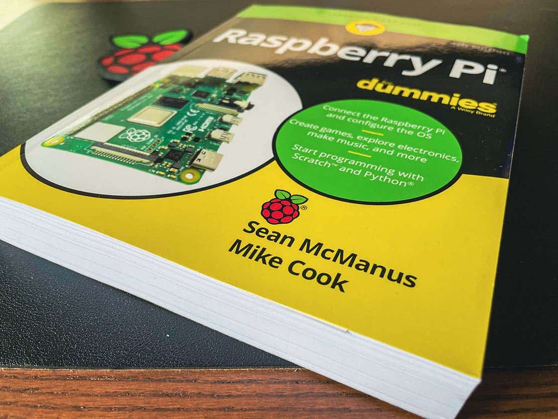
Raspberry Pi for Dummies (1st Edition) was first launched back in 2013, written by Sean McManus and Mike Cook – now veterans of the Raspberry Pi world, and the book soon became a popular resource for those starting out with their new Raspberry Pi. Fast forward 8 years and their book would see the release of the 4th Edition to include updates along with guides that take into account the newer Raspberry Pi 4 boards.

Why a book? Everybody has heard of Google right…?
A perfectly good question and yes, you may well be able to get by with some Google-fu. However, having a book that you can reference is always useful not only because it’s often easier to follow, but also because you can make notes and highlight areas of interest to you. And with 488 pages of material, you’ll have plenty to get through and learn.
The 4th Edition of Raspberry Pi for Dummies covers all bases when it comes to getting to grips with your favourite single board computer, such as “Setting Up Your Raspberry Pi”, “Programming the Raspberry Pi” and the always interesting “Using the Raspberry Pi for Both Work and Play” covers a number of daily use cases that every beginner should try.
If you like something a little more interactive with the real-world, then you should check out the “Exploring Electronics with the Raspberry Pi” section as you start to familiarise yourself with building simple electronic circuits and using the Raspberry Pi’s GPIO (General Purpose Input/Output) pins. The chapter on “Old McDonald’s Farm and Other RFID Adventures” is particularly interesting as you start to see how a Raspberry Pi can be used in the real world. Fancy learning a new programming language? Then why not take a look at Chapter 9, “Introducing Programming with Scratch” which covers all you need to know in order to start programming right there on your very own Raspberry Pi.

Is “Raspberry Pi for Dummies (4th Edition)” worth buying?
Whilst the 488 page book might seem a little daunting to the beginner, don’t let that put you off investing in this book. Not only does the latest edition cover the basics, meaning somebody who has just picked up their first Raspberry Pi can get up and running in no time at all, thanks to Sean and Mike’s helpful and plain English approach to their guides, but it also delves deeper into other areas such as “Getting Started with Linux” (where I even picked up some helpful tips and tricks) so that you can really start exploring with confidence.
The book follows the “for dummies” tried-and-tested approach, which provides simple and helpful explainer sections along the way, and the steps are clearly outlined and written in an easy-to-follow way. This makes it an excellent investment to anybody starting out in the Raspberry Pi world. Not only does this take the hassle out of learning, but it makes the process more enjoyable as you start to learn more as you go. Oh and it’s also troll-free because it’s a good old-fashioned textbook!
I can definitely see this book fast becoming a popular choice for those entering the Raspberry Pi community. Pick up a copy (no affiliate links here by the way) over on Wiley (via Amazon) or via Sean’s website directly.
]]>
If you have already seen my Raspberry Pi Night Vision Camera Hack, then you’ll already know I have been using a Raspberry Pi and NoIR camera module for home security purposes and have been able to combine IR LEDs to provide an additional light source for use in the dark or at night.
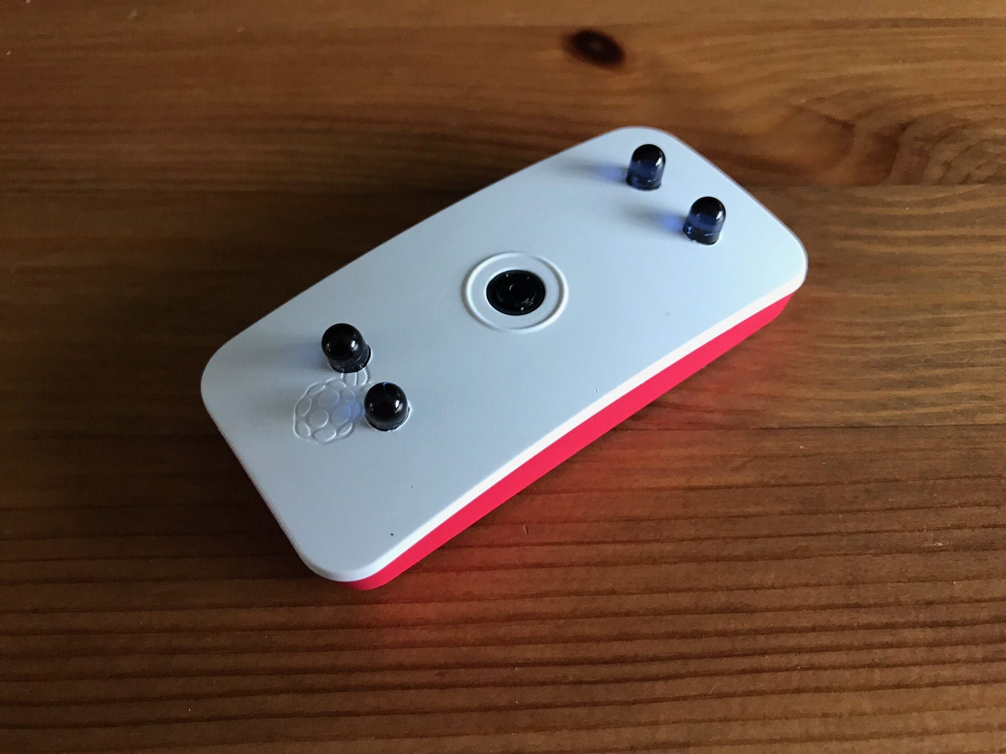
However, since the Pi Zero W and official Raspberry Pi Zero case was released, the small size makes for a perfect camera setup. My wife and I are expecting our first baby in December, and as first time parents we are currently being bombarded with advice and guidance on what to do. One seemingly common purchase seems to be a night vision baby monitor, but I’m surprised by the high cost for these devices and felt like I could build my own version instead.
Add IR LEDs to a Pi Zero W
Being able to improve the night vision of a NoIR Raspberry Pi Camera Module is a frequently asked question online, and the results can vary. Unless you opt for an externally powered infrared light source, then providing additional illumination in the dark is a little tricky, especially if you want to see objects further away. However, as I am planning on using this as a Raspberry Pi powered night vision baby monitor and will have this in close proximity to where our son will sleep, then adding a few infrared LEDs to provide some additional light at night should be a marked improvement.
For this project, I used the following parts:
- Raspberry Pi NoIR Camera Module v2
- Official Raspberry Pi Zero case with the camera cover
- Raspberry Pi Zero W
- 4 x 5mm IR LEDs
- 4 x 220 Ohm resistors
- Prototyping wire
- Soldering iron and solder
- Heatshrink
It also goes without saying that a decent Raspberry Pi power supply should be used, ideally the official PSU that provides at least 2.5A. There is some soldering involved with this project, and it is a little intricate at times due to the small parts being used, but it always helps to use a breadboard and build and test the circuit first:

In my circuit, I connected the LEDs to individual GPIO pins on the Pi Zero (BCM 17, 18, 22 and 27) and then the ground to any of the ground pins as it doesn’t matter which one.
Soldering the circuit
Once you are satisfied that the circuit works, you can start soldering it permanently. This is a little daunting for beginners, but practice makes perfect, so maybe start by following some of the various soldering guides on the Raspberry Pi website to hone your skills.
I used a 5mm drill bit and slowly drilled 4 holes in the case lid, making sure they were out of the way of the camera module and the CSI cable connector – this was very simple and only took me a few minutes.
The trickiest bit for me was connecting the resistors to the same ground wire, and ensuring I didn’t use too much wire as space is a premium inside the case itself. I used some heatshrink on the wires and solder joints to ensure they were insulated in case they came into contact with anything on the Pi Zero itself:
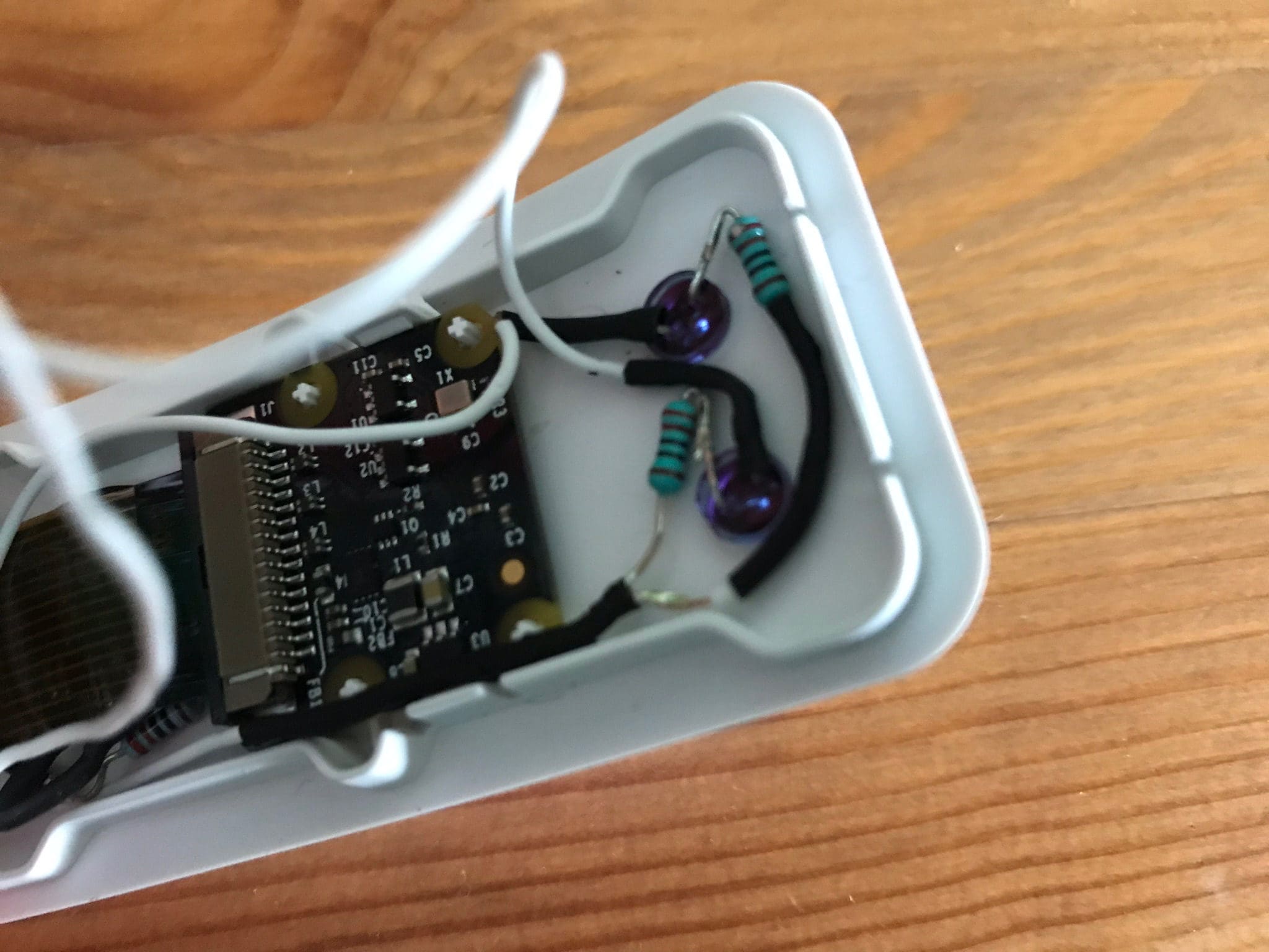
As you can see above, the circuit is quite small and fiddly, but with patience and planning I was able to make it fit nicely:

The code
Now, this is all well and good but to get the IR LEDs working, we need to use a basic Python script. I recommend creating this yourself using your favourite text editor directly on your Pi:
#!/usr/bin/python

import RPi.GPIO as GPIO
import time

# Set up the GPIO -
# mode, and pins

GPIO.setwarnings(False)
GPIO.setmode(GPIO.BCM)
GPIO.setup(4, GPIO.OUT)
GPIO.setup(17, GPIO.OUT)
GPIO.setup(18, GPIO.OUT)
GPIO.setup(27, GPIO.OUT)
GPIO.setup(22, GPIO.OUT)

# Assign a state to the GPIO
# True means the LEDs will be
# on until the script terminates.

state = True

try:
    while True:
      GPIO.output(4,True)
      GPIO.output(17,True)
      GPIO.output(18,True)
      GPIO.output(27,True)
      GPIO.output(22,True)

# Allows you to manually terminate the
# script by pressing 'Ctrl+C'.

except KeyboardInterrupt:
  print('\nStopped')

# Clean up the GPIO - will set back
# to default - i.e. off.

finally:
  GPIO.cleanup()
IR LEDs in MotionEye OS
MotionEye OS is fantastic, and I use it on a few Pi’s at home for CCTV purposes. You can use MotionEye OS to trigger scripts you’ve created by placing them in the/data/etc folder and making sure they are executable. More information on how to do this can be found on my guide on Adding Push Notifications to MotionEye OS, so I won’t go into detail here.
However, I’m going to be using cron to turn run the Python script that controls the IR LEDs so that they turn on when it is darker. Again, this is covered in detail over on the MotionEye OS wiki, so I won’t go into too much detail here.
Example images
Below are some example images, showing what the view is like before and after adding the IR LEDs. As you can see, it is hardly going to light up an entire room, but if you are focussing on something relatively close-by (such as a sleeping baby), then this should work just fine.
Raspberry Pi NoIR Camera before IR LEDs are on:

Raspberry Pi NoIR Camera with the IR LEDs turned on:

So there we have it – a relatively simple DIY project to add some night time illumination to Raspberry Pi NoIR Camera Module within the official Raspberry Pi Zero case.
]]>
We recently moved offices at work as we have been expanding over the last 12 months, and outgrew our old office. Our new office is fantastic and has its very own Garden Room, where we have a picnic bench, Astro-turf flooring and, until recently, two office plants (named Sven and Elizabeth).

However, as with any office there are times where people neglect the simple things and our office plants were the unfortunate victims here. Everybody was under the assumption that somebody else was watering the plants, which sadly was not the case. After a number of weeks without water, one of our office plants died and ended up in the compost heap in the sky but the other (Sven) was clinging to life, and with some watering has slowly returned to its former glory.
Now when you work for a software development company, if there is an excuse to use something involving tech or code then we often will. Throwing myself into the mix, and my passion for Raspberry Pi, then if I have the excuse to use one at work then I will!
Raspberry Pi soil moisture sensor
I’ve come across Raspberry Pi soil moisture sensors before, but I’ve never really had the use-case to buy one. Until now. Our office plants plant means a lot to our MD’s wife – so much so that each plant was named Elizabeth and Sven respectively (as you do) – as they used to be in her office and she donated them to us when she moved out. As you can imagine, she was not best pleased that one of the plants died (Elizabeth) and I thought that this would be the perfect case to whip out a spare office Raspberry Pi and put together a simple Python script that uses our preferred in-work chat tool, Slack.
For those of you who have not heard of [icon name=”slack” class=”” unprefixed_class=””] Slack, it is a chat system that is perfect for in-office communication, especially if you want to cut out the unnecessary email conversations. It is also useful for collaboration – in fact, I’m in a Slack group with other Raspberry Pi fans and coders including the talented likes of Alex Ellis, Richard Gee and Ryan Walmsley to name but a few and it is really helpful when bouncing ideas of each other.
Inspiration for the project
After a quick search online for Raspberry Pi soil moisture sensors projects, I came across a relatively old post on ModMyPi about using the soil moisture sensor in combination with email to notify you when to water the plant.
I thought that this would be a great place to start, so I took parts from their script and added my own parts to help call a Slack webhook to send notifications to our office Slack channel whenever the soil moisture is too low.
Update: 13 September 2017
Having ran the initial code for at least 24 hours, I soon realised that the Slack webhook was being triggered almost constantly for some reason. This happened at 5AM, so there were hundreds of Slack messages about the plant needing to be watered, which not only annoyed my colleagues, but it also made me think about how often the script should be run.
This morning, I re-wrote the script to use a simpler approach to triggering the Slack webhook – in short, I made use of the Raspberry Pi Zero W’s internal pull-up resistors and simply wrote the Python script to check if this changed, rather than looking for a complete state change either way. I also felt that almost constant checking of the soil moisture was over-the-top, so I have tweaked the sleep times to every 15 minutes if the soil is moist, and every 45 minutes if the soil is dry. I’m not too fussed if the plant doesn’t need watering, so I thought this would make more sense.
The code has now been updated to reflect these changes.
Required parts
For my project, I used the following parts:
- Raspberry Pi Zero W (for size and convenience)
- A soil moisture sensor (available on ModMyPi and eBay)
- A Slack account
- A custom webhook integration on Slack
- My code on GitHub.
Connect the soil moisture sensor
This is very simple. There are two connections on the fork shaped part (that goes into the soil) marked positive and negative – simply connect these to the sensor module part. It doesn’t matter which of the two pins you use. Whilst there are 4 pins on the part of the sensor module that connects to your Raspberry Pi, you only need 3: VCC, GND and D0. Connect these as follows:
- VCC to pin 1 on the Pi (3.3v)
- GND to pin 9 on the Pi (Ground)
- D0 to pin 11 on the Pi (GPIO 17).
If connected correctly, you should see at least 1 LED light up on the sensor module. If you then stick the fork end into a glass of water (only the prongs, not the entire module!), you should then see a second LED light up on the sensor module. If you don’t, go back and check your connections – try swapping the two from the fork to the sensor module around first.
Calibrate the soil moisture sensor
There is a small potentiometer on the sensor module that allows you to calibrate the sensitivity of the sensor. The best way to do this is to insert the prongs of the fork into the soil and then slowly turn the potentiometer until 1 LED goes off, this means that when the soil moisture drops to this level, the script will be triggered and alert you via Slack that it needs watering.
Clone my code on GitHub
Obviously you’ll need the code, so clone this on your Raspberry Pi by running this in your command line:
$ git clone git://github.com/raspberrycoulis/plant-hydro-slack.gitIf you want to see what the code looks like, then you can also use this:
#!/usr/bin/python

#####################################################################################
# This was inspired by a guide on ModMyPi (http://bit.ly/mmpsms).                   #
#                                                                                   #
# Use a soil moisture sensor and a Raspberry Pi to monitor the soil in a plant pot  #
# and warn the office, via Slack, that it needs watering.                           #
#                                                                                   #
# By Wesley Archer (@raspberrycoulis - https://www.raspberrycoulis.co.uk)           #
#####################################################################################

# Import the necessary libraries:
import RPi.GPIO as GPIO
import time
import httplib, urllib
import urllib2
import json

# Set the GPIO mode:
GPIO.setmode(GPIO.BCM)

# Define the GPIO pin that the moisture sensor (D0 on the sensor) is connected to:
channel = 17

# Set the GPIO pin above as an input and set the internal pull-up resistor down:
GPIO.setup(channel, GPIO.IN,pull_up_down=GPIO.PUD_DOWN)

# Slack webhook - get this from https://api.slack.com/custom-integrations/incoming-webhooks
webhook_url = "ADD_HERE"

# This is the function that calls the Slack webhook to notify you:
def postToSlack():
    data = '{"attachments":[{"fallback":"Water plant!","pretext":"The soil is too dry!","color":"#cc0000","fields":[{"title":"The Garden Room plant needs watering!","short":false}]}]}'
    slack = urllib2.Request(webhook_url, data, {'Content-Type': 'application/json'})
    post = urllib2.urlopen(slack)
    post.close()

# Run the code in an infinite loop. If the soil is dry, a Slack notification is triggered:
while True:
    if GPIO.input(channel)==False:
        #print('Soil is moist')     # Uncomment to print console commands
        time.sleep(900)             # Sleep for 15 minutes (900 seconds)
    else:
        #print('Soil is dry!')      # Uncomment to print console commands
        postToSlack()               # Trigger the Slack webhook notification
        time.sleep(2700)            # Sleep for 45 minutes (2700 seconds)
Edit the code to use your Slack webhook
After you have created your webhook integration in Slack, you’ll need to edit the Python script accordingly:
$ cd plant-hydro-slack
$ nano dry-to-slack.py
Find the variable on line 29 called webhook_url and then replace "ADD_HERE" with your Slack webhook URL. Then save and exit:
$ CTRL+X
$ Y
Your script is now good to go.

Running the script automatically on boot using systemd
In order to run the script automatically when the Raspberry Pi boots, I recommend using systemd to run it as a service:
$ sudo nano /lib/systemd/system/moisturesensor.serviceThen add the following:
[Unit]
Description=Plant soil moisture sensor service
After=multi-user.target

[Service]
Type=idle
ExecStart=/usr/bin/python /home/pi/plant-hydro-slack/dry-to-slack.py > /home/pi/plant-hydro-slack/dry-to-slack.log 2>&1
Restart=always

[Install]
WantedBy=multi-user.target
The parts to check are the ExecStart command as this assumes the dry-to-slack.py script is located in /home/pi/plant-hydro-slack so please update accordingly if you have installed the script in a different location.
Once you have done this, Ctrl+X to exit and Y to save then run:
$ sudo chmod 644 /lib/systemd/system/moisturesensor.service
$ sudo systemctl daemon-reload
$ sudo systemctl enable moisturesensor.service
You can sudo reboot or simply run sudo systemctl start moisturesensor.service to start the script. Check the status by running sudo systemctl status moisturesensor.service.
Taking it further
Now I have an understanding of how webhooks can be triggered by a Python script on a Raspberry Pi, I thought about how else they could be used. One idea that I currently use in the script in our office is to utilise the IFTTT Maker Webhooks channel to trigger an update to a Google Sheet, keeping track of all the time the soil is moist but without annoying everybody with constant Slack messages.
Create the IFTTT Maker Webhook
You’ll need a free IFTTT (If This Then That) account first, then you’ll need to activate the Maker Webhook channel. Once you do this, create a new applet and use the Maker Webhook as the “If This” part. Set a trigger keyword, as this will form the basis of the webhook and then set an action for the “Then That” section of your applet. In my example, I chose to add a new row to a Google Sheet under the Google Drive action.
You can add variables if you want, but I didn’t see the need for this so I just continued without them. You can find the webhook you’ll need by clicking on the “Documentation” button on the Maker Webhook channel, and test it works by substituting your trigger word in the appropriate box. For example:
$ curl -X POST https://maker.ifttt.com/trigger/{event}/with/key/{your_unique_key}You actually want only the URL, so ignore the “curl -X POST” part. Copy this as you’ll need it later.
Modify the code
To use the new webhook, I edited my code and added a new function:
$ nano dry-to-slack.pyThe code now looks like this:
#!/usr/bin/python

import RPi.GPIO as GPIO
import time
import httplib, urllib
import urllib2
import json
import requests

GPIO.setmode(GPIO.BCM)
channel = 17
GPIO.setup(channel, GPIO.IN,pull_up_down=GPIO.PUD_DOWN)

# Slack webhook
webhook_url = "ADD_HERE"

# IFTTT Maker Webhook
ifttt_url = "ADD_HERE"

def postToSlack():
    data = '{"attachments":[{"fallback":"Water plant!","pretext":"The soil is too dry!","color":"#cc0000","fields":[{"title":"The Garden Room plant needs watering!","short":false}]}]}'
    slack = urllib2.Request(webhook_url, data, {'Content-Type': 'application/json'})
    post = urllib2.urlopen(slack)
    post.close()

def IFTTT():
    requests.post(ifttt_url)

while True:
    if GPIO.input(channel)==False:
        print('Soil is moist')
        IFTTT()
        time.sleep(900)
    else:
        print('Soil is dry!')
        postToSlack()
        time.sleep(2700)
To get this working, you’ll also need to install a couple of modules on your Pi:
$ sudo apt-get install python-pip
$ sudo pip install requests
This will install the PIP Python module, and then use PIP to install the requests module required for the IFTTT webhook to be triggered. You can then test it out by running:
$ ./dry-to-slack-ifttt.pyYou should then see wither “Soil is moist” or “Soil is dry!” in the console, and if it is the former you will see a new row on a new Google Sheet with the date and time, as well as the trigger keyword, or if it is the latter, you should get a Slack notification telling you to water the plant.
Running the systemd service at set times
One other issue I noticed was that the code would run constantly, and could trigger Slack messages during the early hours or over a weekend when nobody is about. This would soon become annoying, so one simple method I used is to trigger the service to start and stop using crontab:
$ sudo crontab -eThen add the following two lines:
# Start Plant Soil Moisture Monitoring Service every weekday at 8:00am
00 08 * * 1-5 systemctl start plant-moisture.service

# Stop Plant Soil Moisture Monitoring Service every weekday at 9:30pm
30 21 * * 1-5 systemctl stop plant-moisture.service
I always find Crontab Guru really useful when creating cron jobs as I can be 100% confident they will run at the time I want.
Exit (CTRL+X) and save (Y) to install the new crontab.
There may be more elegant ways of running the script at designated times, but I didn’t know how. I’m happy to take any suggestions though!
]]>Slack notifications on Raspberry Pi

For those of you who haven’t heard of or used Slack, it is a great communication tool that is used in many modern workplaces. It is a chat tool that reduces the dependence on emails, and allows for quicker more efficient communication in the office.
The beauty of Slack is that it is free to use (there is a paid-for subscription for enterprise level usage) but can be integrated with a wide variety of third-party applications, as well as being able to utilise incoming and outgoing webhooks.
Slack controlled On-Air sign
This is an example of how I use Slack every day at work in my job. As I often speak to important enterprise customers, often from other countries, I found that it often became noisy whenever the guys upstairs needed to grab another cup of coffee. Being a fan of all things IoT, I decided to build an On-Air sign that could be controlled via Slack, so that I could quickly turn the sign on whenever I was on an important call. I’ll be writing up a separate post on this particular project, but being able to control it via slash commands in Slack was really useful and we now use it every time we have a conference call with a customer.
This (pretty badly shot) video, should give you an idea of what is to come when I get the project on here:
Raspberry Pi Twitter Follower Bot
I tend to check how many Twitter Followers I have every now and then, as I’m always looking to spread the word about Raspberry Pi and Raspberry Coulis where possible. I then thought it would be pretty nice if I could automate this process using a Raspberry Pi and some Python code.
To save making this post unnecessarily long, I have included detailed instructions in the README.md file on my GitHub repository which will guide you through the necessary parts, but if you are after the code then here it is:
#!/usr/bin/python

import tweepy
import urllib2
import time

# For Twitter: Add the relevant keys, tokens and secrets from your Twitter app made here: https://apps.twitter.com/

consumer_key = ''
consumer_secret = ''
access_token = ''
access_token_secret = ''

# Variables - configure the bits below to get your script working.

wait = 12600        # Time (in seconds) between checks. Default is 12600 seconds (210 minutes / 3.5 hours).
style = "#1da1f2"   # Colour for the message - default is Twitter Bird blue
userid = ''           # The Twitter user you want to track the followers of (without the @)
handle = ''         # Tweak this to display the userid in a nicer format - i.e. "Raspberry Coulis" instead of "raspberrycoulis"

# Slack incoming webhook URL

webhook = ''

# Tweepy API - do not change
auth = tweepy.OAuthHandler(consumer_key, consumer_secret)
auth.set_access_token(access_token, access_token_secret)
api = tweepy.API(auth)
follows = api.get_user(userid)

# The function that does the magic - checks your Twitter user for the number of followers then sends this data to Slack to notify you.

def postToSlack():
#  while True:
    fans = str(follows.followers_count)
    data = '{"attachments":[{"fallback":"'+handle+' has '+fans+' followers.","pretext":"'+handle+' has '+fans+' followers.","color":"'+style+'","fields":[{"title":"Twitter Fans","value":"'+handle+' has '+fans+' followers.","short":false}]}]}'
    slack = urllib2.Request(webhook, data, {'Content-Type': 'application/json'})
    f = urllib2.urlopen(slack)
    f.close()
#    time.sleep(wait)

postToSlack()

exit()
If all goes well, you should receive a Slack notification telling you how many followers your account has!

As I’m still learning Python and all things Raspberry Pi related, I’d welcome any feedback on this code via my Gist.
Raspberry Pi Facebook Fan Bot
In similar fashion to the Twitter Follower Bot above, the Facebook Fan Bot works in a very similar way. The great thing about this script is that you only need to add a few access keys, secrets and ID’s to get it working.
Again, to save repeating myself in here, take a look at the README.md on my GitHub repository that tells you how to get and add the necessary keys and IDs to your script. This is what it looks like:
#!/usr/bin/python

import urllib2
from urllib import quote
import json

# Variables - configure the bits below to get your script working.

style = '#3b5998'   # Colour for the message - default is Facebook blue
fb_page = ''        # Facebook Page name

# Slack incoming webhook URL

webhook = ''

# The functions that creates the magic - checks your Facebook Company Page for the number of fans then sends this data to Slack to notify you.

def fanCount():
    fb_id, app_id, secret = '', '', ''      # Add your Page ID, App ID and Secret between each quotation mark
    fb_url = 'https://graph.facebook.com/{}?access_token={}|{}&fields=fan_count'.format(quote(fb_id), quote(app_id, quote(secret))
    fanCount = urllib2.urlopen(fb_url).read()
    jsonResponse = json.loads(fanCount)
    return jsonResponse['fan_count']

def postToSlack():
    fb_fans = str(fanCount())
    data = '{"attachments":[{"fallback":"'+fb_page+' has '+fb_fans+' followers.","pretext":"'+fb_page+' has '+fb_fans+' followers.","color":"'+style+'","fields":[{"title":"Facebook Fans","value":"'+fb_page+' has '+fb_fans+' followers.","short":false}]}]}'
    slack = urllib2.Request(webhook, data, {'Content-Type': 'application/json'})
    f = urllib2.urlopen(slack)
    f.close()

postToSlack()

exit()
And if successful, you should get another Slack notification that looks like this (assuming you have added the custom icons included in my repository):

If you would like to provide your feedback, please feel free to do so via my Gist.
Automating Slack Notifications on Raspberry Pi
Rather than have these scripts run constantly, bombarding your with Slack notifications, it may be better to schedule them via cron to run at specific times of the day. Unless you are uber-popular, like the official Raspberry Pi Twitter account, then checking on your followers once or twice a day ought to be enough.
Cron can appear confusing at first, but if you use a crontab generator then this whole process is a lot easier to manage. In my setup on my Raspberry Pi, I have my Twitter Follower Bot and Facebook Fan Bot checking in the morning and in the evening, which is perfectly adequate for me.
]]>
I’ve always been one for tinkering and trying something new when it comes to the world of technology. Those of you who follow this site and my X (formerly Twitter) ramblings announcements will notice I like to get involved and share my knowledge where possible.
Ghost
Now, I’m not getting all spiritual on you here – I’m talking about the blogging platform called Ghost. It is a relatively new blogging platform, that is lightweight and easy to use, and perfect for installing and hosting on a Raspberry Pi - in fact, this website is now hosted on Ghost after moving from WordPress!
Rather than repeat what I have already done, I would like to direct you all to my very own Ghost blog. Aptly named Ghost Pi, my blog details how to install and run Ghost on a Raspberry Pi, and is hosted on a Raspberry Pi 3.
So why not head on over and check it out?
]]>

If you are a regular reader of The MagPi Magazine (and let’s be honest, why wouldn’t you be if you’re a Raspberry Pi fan?), you may have noticed that for five issues, there was a step-by-step guide on How To Build Your Own DIY Arcade Machine, which was written by yours truly! In fact, I called the build a RaspCade just because.
I have been a big gamer ever since my parents bought me the Nintendo Entertainment System back in nineteen-ninety-something, and if you have seen my Raspberry PiStation build, you’ll start to realise this too. And when I was younger, I was always fascinated by the lure of arcades – games like Teenage Mutant Hero (Ninja to my US readers) Turtles, The Simpsons, Street Fighter II, Captain Commando, Metal Slug etc. are just some games that I remember pumping money into whenever I had the chance.
As such, I’ve always wanted an arcade machine at home but I didn’t have the cash to be able to buy one. I was very close to taking the plunge and buying Pimoroni’s Picade, but I thought it might be fun to try and build my own – especially as I had lots of parts lying around that could be used to do just that! This is how my RaspCade was born.
Not another arcade build…
Yes, I hear the sighs. I know there are many Raspberry Pi arcade builds out there, but a lot of them I come across involve complex cabinet designs, or vast amounts of money to make it look professional. I wanted something that I could make myself, but also be able to share openly with other gamers and Raspberry Pi fans. As such, I decided to design my own arcade cabinet that could be laser cut by anybody – and rather than charge for the plans, made them free to download!
It took me a few attempts to get the RaspCade cabinet design just right, but I’m not saying it is perfect. However, as my plans are open source, you can customise them as you see fit! However, I’m pretty pleased with the outcome:

Once you have the designs, you can use a laser cutting service to get your very own RaspCade arcade cabinet! I used the very helpful Just Add Sharks (UK based), and it cost me around £15 including delivery, which I thought was very reasonable! You can also use places like Ponoko (good for US based makers) too.
RetroPie
Now, it is not surprising to learn that I used the fantastic RetroPie on my RaspCade. It is very simple to install now, and also comes with an ever-growing wiki and support community, which is really helpful if you get stuck. I downloaded the SD card image from RetroPie, flashed it to my SD card and booted the Pi (Raspberry Pi 3 for the best bang for your buck) and I was almost good to go straight away. I needed to change the display resolution, tweak the audio output and configured the controls, but this is all simple to do. I won’t cover this here as the RetroPie wiki covers everything you need.
Custom boot screen

There is no point doing all this work to use the standard boot screens used by RetroPie, so I decided to create my own to use instead. If you want to use them, please feel free as I’ve made them available to download for free as part of this build.
NeoPixel Arcade buttons
I wanted to make my RaspCade look a bit flashy, so I thought it might be cool to use LED’s to illuminate the buttons. However, I didn’t want to splash out on the standard illuminated arcade buttons and fancied making my own. My plan was to use some NeoPixels and integrate them within each arcade button using a custom 3D printed holder. I was inspired by a post I read over on Adafruit, so I decided to give it a go for myself! Once I had the 3D printed parts (I used Hubs, and went with Steelmans 3D Print in the end and was really pleased with the results).

To power my NeoPixels (individual PCB versions for those wanting to give it a go), I used a Particle Photon as I wanted to be able to control the lights over the Internet, so this made a perfect option to make them IoT. I used my Particle Photon in combination with IFTTT and created various commands so that I could activate them via the IFTTT app on my iPhone. I would like to take this opportunity to thank the magnificent Frederick Vandenbosch too – he helped me tweak his code for his IoT Tower Light to create the code I ended up using in mine.
Here is the code I ended up using in my RaspCade:
#include "application.h"
#include "neopixel/neopixel.h"

SYSTEM_MODE(AUTOMATIC);

#define PIXEL_PIN D2
#define PIXEL_COUNT 6
#define PIXEL_TYPE WS2812
#define BRIGHTNESS 50

Adafruit_NeoPixel strip = Adafruit_NeoPixel(PIXEL_COUNT, PIXEL_PIN, PIXEL_TYPE);

int animation = 0;

void setup()
{
  strip.setBrightness(BRIGHTNESS);
  strip.begin();
  strip.show();

  Particle.subscribe("animation", myHandler);
}
void loop()
{
  switch (animation)
  {
    case 0: //OFF
      strip.setPixelColor(0, strip.Color(0, 0, 0));
      strip.setPixelColor(1, strip.Color(0, 0, 0));
      strip.setPixelColor(2, strip.Color(0, 0, 0));
      strip.setPixelColor(3, strip.Color(0, 0, 0));
      strip.setPixelColor(4, strip.Color(0, 0, 0));
      strip.setPixelColor(5, strip.Color(0, 0, 0));
      break;
    case 1: //NES: All Red
      strip.setPixelColor(0, strip.Color(255, 0, 0));
      strip.setPixelColor(1, strip.Color(255, 0, 0));
      strip.setPixelColor(2, strip.Color(255, 0, 0));
      strip.setPixelColor(3, strip.Color(255, 0, 0));
      strip.setPixelColor(4, strip.Color(255, 0, 0));
      strip.setPixelColor(5, strip.Color(255, 0, 0));
      break;
    case 2: //Sega: Cyan and Blue
      strip.setPixelColor(0, strip.Color(0, 255, 255));
      strip.setPixelColor(1, strip.Color(0, 255, 255));
      strip.setPixelColor(2, strip.Color(0, 255, 255));
      strip.setPixelColor(3, strip.Color(0, 0, 255));
      strip.setPixelColor(4, strip.Color(0, 0, 255));
      strip.setPixelColor(5, strip.Color(0, 0, 255));
      break;
    case 3: //Raspberry Pi - Raspberry Red & Leaf Green
      strip.setPixelColor(0, strip.Color(165, 55, 56));
      strip.setPixelColor(1, strip.Color(165, 55, 56));
      strip.setPixelColor(2, strip.Color(165, 55, 56));
      strip.setPixelColor(3, strip.Color(118, 169, 40));
      strip.setPixelColor(4, strip.Color(118, 169, 40));
      strip.setPixelColor(5, strip.Color(118, 169, 40));
      break;
    case 4: //SNES UK: White, Blue, Green, Yellow, Red, White
      strip.setPixelColor(0, strip.Color(255, 255, 255));
      strip.setPixelColor(1, strip.Color(0, 0, 255));
      strip.setPixelColor(2, strip.Color(0, 255, 0));
      strip.setPixelColor(3, strip.Color(255, 255, 0));
      strip.setPixelColor(4, strip.Color(255, 0, 0));
      strip.setPixelColor(5, strip.Color(255, 255, 255));
      break;
    case 5: //SNES US: Light Purple & Dark Purple
      strip.setPixelColor(0, strip.Color(160, 100, 255));
      strip.setPixelColor(1, strip.Color(160, 100, 255));
      strip.setPixelColor(2, strip.Color(160, 100, 255));
      strip.setPixelColor(3, strip.Color(100, 0, 255));
      strip.setPixelColor(4, strip.Color(100, 0, 255));
      strip.setPixelColor(5, strip.Color(100, 0, 255));
      break;
    case 6: //Orange
      strip.setPixelColor(0, strip.Color(255, 125, 0));
      strip.setPixelColor(1, strip.Color(255, 125, 0));
      strip.setPixelColor(2, strip.Color(255, 125, 0));
      strip.setPixelColor(3, strip.Color(255, 125, 0));
      strip.setPixelColor(4, strip.Color(255, 125, 0));
      strip.setPixelColor(5, strip.Color(255, 125, 0));
      break;
    default: //NES: All Red
      strip.setPixelColor(0, strip.Color(255, 0, 0));
      strip.setPixelColor(1, strip.Color(255, 0, 0));
      strip.setPixelColor(2, strip.Color(255, 0, 0));
      strip.setPixelColor(3, strip.Color(255, 0, 0));
      strip.setPixelColor(4, strip.Color(255, 0, 0));
      strip.setPixelColor(5, strip.Color(255, 0, 0));
  }
  strip.show();
}

void myHandler(const char *event, const char *data) {
    animation = atoi(data);
}
You can use an Adafruit Trinket 5V too, but you just won’t be able to control them online, and there are some tweaks needed to the code but I won’t cover that here at the moment.
The MagPi Magazine
So, if you would like to follow the build step-by-step, then you should definitely check out issues 47 to 51 of The MagPi Magazine. All back issues are free to download, plus you can also check out other fantastic Raspberry Pi projects too and not just my RaspCade build!
However, if you would like to download just my RaspCade build and the 5 parts, then you can do just that! I have added my 5 parts into one PDF so that you can follow the build step-by-step.
So there we are! A DIY RaspCade – a Raspberry Pi powered arcade machine that you can make for yourself!
]]>
Now that the Raspberry Pi Zero is easier to get hold of, it makes an ideal choice for a portable car audio player if paired with a suitable DAC, or Digital Analogue Converter.
If you have seen my post on the Raspberry Pi Audio Player then you will have seen that there are multiple OS’s offering slick user interfaces and support for many of the Raspberry Pi compatible DAC’s on the market. As a result, I have been using mOode Audio, combined with my Raspberry Pi B+ and IQ Audio’s Pi-DAC+ for some time now and I have been impressed with the result.
However, I recently bought a newer car that had a USB port and auxiliary connector in the driver’s arm rest which got me thinking. I could use the OEM iPod USB cable (that costs £50 from BMW, I kid you not!), risk a knock off but potentially working cable from eBay, or go full-hog and use this as an excuse to install a Raspberry Pi accompanied with a suitable DAC and upgrade my driving audio experience in one hit? Well, it would be a bit stupid to write a guide on a Raspberry Pi guide website about an iPod cable wouldn’t it?!
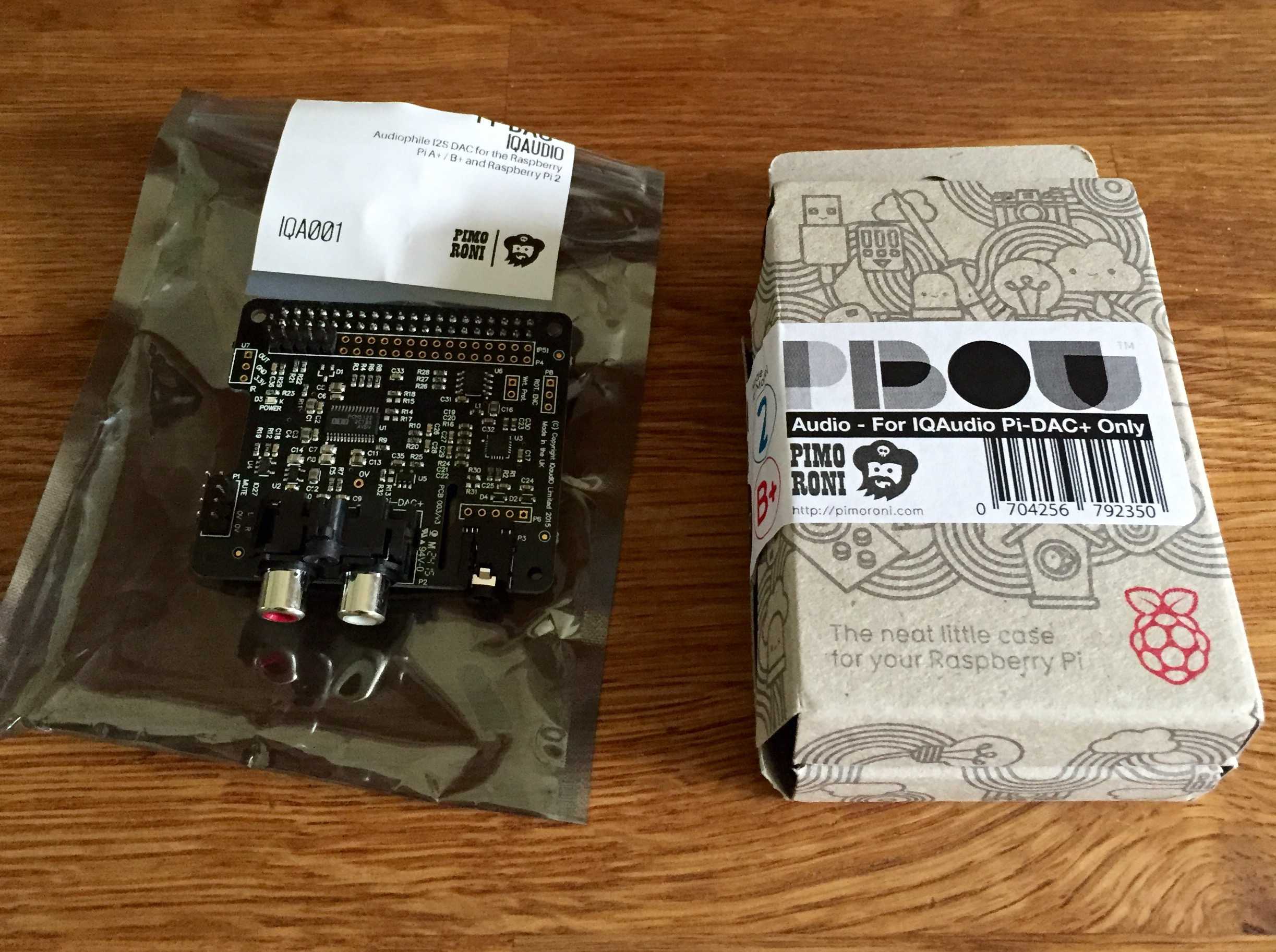
Enter Pimoroni’s pHAT DAC
The team at Pimoroni are naughty people. They keep making amazing Raspberry Pi accessories that usually results in me spending sums of money with them, then continue enticing me to buy by releasing yet more fantastic goodies! Having seen the pHAT DAC before, I resisted temptation until I had a decent project lined up, and here it is.

Costing no more than twelve English pounds, the pHAT DAC is a fantastic addition to any Raspberry Pi enthusiasts arsenal. With some soldering required to attach the header pins (and to attach the optional phono connectors if needed), you simply pop it onto your Pi, following their installation guide and you’ll soon have it pumping out crisp sound from your Raspbian setup.
However, if you are planning on installing mOode Audio (or Volumio or Rune Audio) then installation is even easier. You attach the pHAT DAC and then select it from within the settings once your Pi has booted and you have opened the user interface in your favourite web browser and hey presto!
mOode Audio, AirPlay and WiFi Access Point
As I am going to be using my Pi in my car, I needed a way of controlling my Raspberry Pi car audio player so when I found out that mOode now creates a WiFi Access Point (AP) that you can connect to as a way of accessing the user interface – all from a fresh install – I was suitably impressed! This is such a cool feature and solved my next problem before it even started!
I need MORE USB ports!
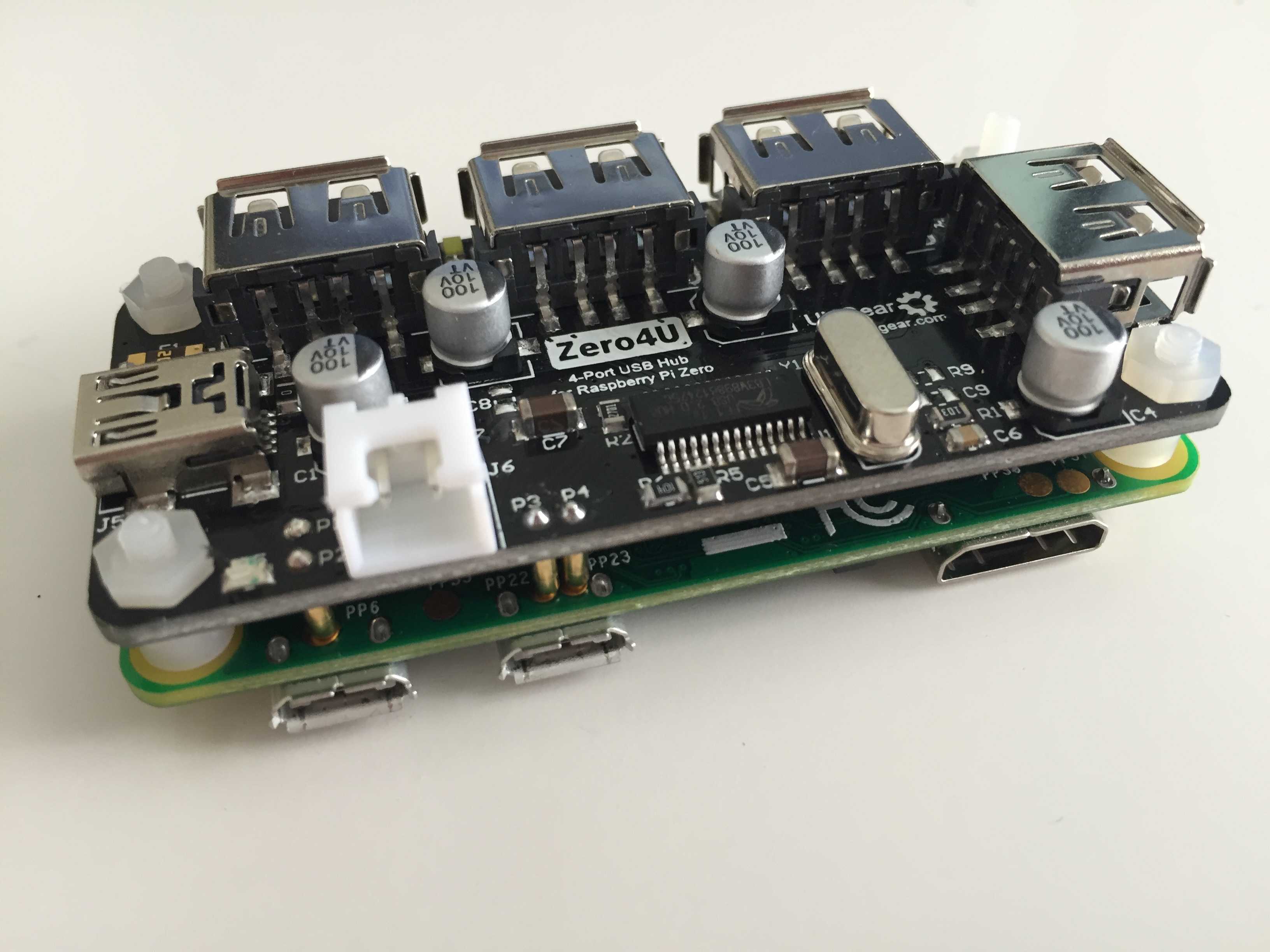
So I have the elusive Pi Zero, Pimoroni’s pHAT DAC and a WiFi AP to connect to, but the problem was now running out of USB ports, especially as I wanted to connect a slimline USB thumb drive to my Pi containing HD audio tracks (as in 24bit, 96-192khz audio). I then remembered that the guys at UUGear kindly sent me their fantastic Zero4U, 4 port Raspberry Pi Zero USB hub which would be perfect for this! If you’re not sure what the Zero4U is, then take a look at my review and see for yourself.

All assembled
As my Raspberry Pi car audio player will be out of sight, hidden in the driver’s arm rest in my car, it did not need to look like a work of art. I did not bother with any form of case, instead being satisfied that the arm rest was small enough to contain the Pi without it rattling around as I drove.
Turning on and off
The last hurdle I needed to overcome was powering up and turning off the Raspberry Pi car audio player safely, without corrupting the SD card. I am well aware of the fantastic, but expensive to buy if you live outside the US, Mausberry Circuit Switch (I have used one of these in my Raspberry PiStation build), but given that installing this in a car requires some tinkering with the car’s electrics, I decided I didn’t want to risk this. Instead, I opted for a micro USB lead with an inline switch. This allows me to manually turn the power on, and once I have stopped and turned off my engine, I can login and shutdown the Raspberry Pi car audio player using the user interface. I can then kill the power using the switch.
Using it
I am really impressed with my setup. Granted it doesn’t look particularly fantastic, but it works excellently. More importantly, the sound quality is much better than an iPod! I tweaked a few options within mOode’s settings, specifically to auto-play on boot, so my music now just picks up from where it left off when I shutdown last. It is a shame that I cannot safely queue up songs whilst driving (especially because I value my license and other road users!), but for a Raspberry Pi car audio player for less than £30, you cannot go wrong!
]]>
Getting WiFi working on Raspberry Pi must be one of the most searched topics since the popular board was released. Thankfully, this is now a pretty simple process even for beginners! However, as the Raspberry Pi is portable, many people like to take it with them wherever they go. This presents a new challenge, which is providing Internet access without access to a monitor or an Ethernet cable. Like other Internet connected devices, people want to set up Raspberry Pi multiple WiFi networks.
Firstly, did you know that there is a quick way to set up WiFi on your Raspberry Pi before the first boot?
Setup Raspberry Pi WiFi Before Boot
Until recently, you had to boot your Pi with an Ethernet cable connected and then make all the necessary edits to system files to setup WiFi. However, there is now a way to setup WiFi before you power on your Pi for the very first time. In order to do this, you need to create a file called “wpa_supplicant.conf” and then transfer it to the boot folder on your SD card. You can do this in any basic text editing software, but Notepad++ is recommended.
Notepad++ is a free text editor and is a suped-up version of the standard Windows Notepad. However, it is great for creating or editing code because it helps with formatting – such as indentation, brackets and so on. You can download Notepad++ from their website.
WPA Supplicant
First, open Notepad++ and add the following code to it:
ctrl_interface=DIR=/var/run/wpa_supplicant GROUP=netdev
update_config=1
network={
    ssid="YOUR_WIFI_NETWORK"
    psk="YOUR_WIFI_PASSWORD"
    key_mgmt=WPA-PSK
}
You need to add your own details to this document, and they are pretty self-explanatory:
- SSID = Your WiFi network name
- PSK = Your WiFi password
Encryption
The last section, “key_mgmt”, is set depending on the encryption method your WiFi network uses. If you are using a relatively modern WiFi router, then the chances are it will be WPA-PSK. For the curious, this stands for WiFi Protected Access Pre-Shared Key. Older routers (as in 10+ years) may use WEP, or Wired Equivalent Privacy, but this is no longer recommended as a relatively inexperienced hacker could crack this in a few minutes if they wanted to!
Once you have added your WiFI network name and password, save your file as “wpa_supplicant.conf” (without the quotation ” ” marks and ensuring it is lower-case). This is what you can now transfer to the boot folder on your SD card. Now when you boot your Pi, it should automatically connect to your WiFi network!
What actually happens is that your Pi copies the “wpa_supplicant.conf” file to the proper location on the Pi itself. This is typically “/etc/wpa_supplicant”, and if you want to make any additional changes, you can find the “wpa_supplicant.conf” file here.

Hang on though!
You have come here because you want to establish Raspberry Pi multiple WiFi networks! To do this, you follow the same steps as above, except you need to add a few more networks to your “wpa_supplicant.conf” file. There is also an additional step required, especially if you want to prioritise the networks so that your Pi prefers to connect to a specific network over another.
Raspberry Pi Multiple WiFi Networks
To do this, you will obviously need to know the details of all the WiFi networks you want your Raspberry Pi to connect to. This may well be your home network, your school or work network and maybe a phone-tethered network (i.e. for when you want to get your Pi online outside the reach of other WiFi networks). Once you have the SSID and passwords for your WiFi networks, you need to add them to your “wpa_supplicant.conf” file:
ctrl_interface=DIR=/var/run/wpa_supplicant GROUP=netdev
update_config=1
network={
    ssid="HOME_WIFI_NETWORK"
    psk="HOME_WIFI_NETWORK_PASSWORD"
    key_mgmt=WPA-PSK
    id_str="home"
    priority=1
}
network={
    ssid="WORK_WIFI_NETWORK"
    psk="WORK_WIFI_NETWORK_PASSWORD"
    key_mgmt=WPA-PSK
    id_str="work"
    priority=2
}
network={
    ssid="PHONE_TETHER_NETWORK"
    psk="PHONE_TETHER_NETWORK_PASSWORD"
    key_mgmt=WPA-PSK
    id_str="phone"
    priority=3
}
If you look carefully at the new details above, you may notice a few things. Firstly, we have created three networks – one for home, one for work and one for tethering to your phone’s WiFi hotspot. In order to help your Raspberry Pi understand which network is which, we have also added the “id_str” string, which you will notice has been assigned a name – either “home”, “work” or “phone”. This is a crucial step for Raspberry Pi multiple WiFi networks, as you will need them for the next part, so remember them.
Setting priorities
You may also notice a “priority” string, along with a number. This is pretty self-explanatory – this tells your Raspberry Pi to try and connect to your networks in a specific order. First of all, the numbers associated are not as logical as you would expect! This is because the higher the number, the higher the preference. In the example above, our Raspberry Pi will try to connect to the networks in the following order:
- Phone (priority of 3)
- Work (priority of 2)
- Home (priority of 1)
As a result, our example places the “phone” network at the top because we may want to connect to our Raspberry Pi in the office, but want to avoid connecting to the “work” network if the “phone” network is present. You might want to experiment with the priorities yourself, and you can do this by simply changing the numbers associated with the “priority” string.
Almost there…
There is one more adjustment required to get Raspberry Pi Multiple WiFi Networks, and that is to add a couple of lines to the “/etc/network/interfaces” file, because this tells your Raspberry Pi how to connect to any networks present:
# interfaces(5) file used by ifup(8) and ifdown(8)

# Please note that this file is written to be used with dhcpcd
# For static IP, consult /etc/dhcpcd.conf and 'man dhcpcd.conf'

# Include files from /etc/network/interfaces.d:
source-directory /etc/network/interfaces.d

auto lo
iface lo inet loopback

iface eth0 inet manual

allow-hotplug wlan0
iface wlan0 inet manual
    wpa-conf /etc/wpa_supplicant/wpa_supplicant.conf

allow-hotplug wlan1
iface wlan1 inet manual
    wpa-conf /etc/wpa_supplicant/wpa_supplicant.conf
iface home inet dhcp
iface work inet dhcp
iface phone inet dhcp
The key lines here are the bottom three:
- iface home inet dhcp
- iface work inet dhcp
- iface phone inet dhcp
Remember the “id_str” names we added earlier? If not, then it might be worth going back and getting them as this is where we add them to our interfaces file. You now just need to add your “id_str” here, along with the prefix “iface” and the suffix “inet dhcp”, especially if your IP addresses are set by DHCP.
Last step!
Once you have added your network strings to the interfaces file, simply save it (do this by pressing Ctrl+X if using Nano) and then reboot your Raspberry Pi! If all goes well, you should have setup Raspberry Pi Multiple WiFi Networks, along with prioritised connections!
]]>
The Raspberry Pi is ideally suited for an Internet of Things project, especially when it comes to home automation. The MagPi Magazine recently featured an advert for myDevices Cayenne, stating it as a drag-and-drop IoT project builder. As with any home automation toolkit, I decided to explore further and share my review here.
So what is it?
Well, myDevices Cayenne is being marketed as a Raspberry Pi IoT (Internet of Things) drag-and-drop project builder. On first inspection it does exactly that. Once installed and setup, you simply drag-and-drop your devices into tasks, events and schedules to get underway.
In order to use myDevices Cayenne, users need to register to create a free account via their website. This requires a valid email address and a password, only takes a matter of seconds. The next step was to download their app, which is available on iOS and Android, which was also free. Once installed, there are detailed installation instructions that helps guide you through the process.

Installation
Getting myDevices Cayenne installed on the Raspberry Pi is pretty simple and it should take less than 10 minutes before you have everything up and running. The app gives you detailed instructions on how to do this, as does their website. The best method is to follow the instructions on their website, which involved adding a new device via their dashboard:
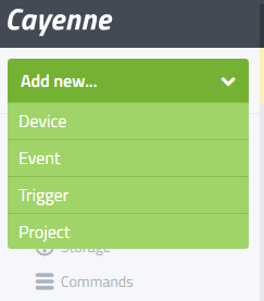
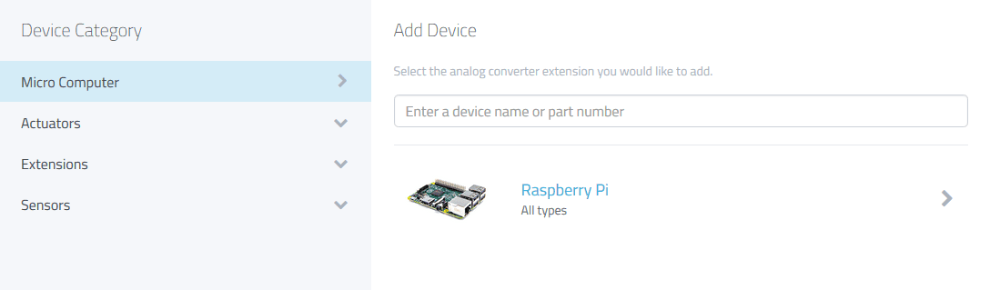
To proceed, select “Device” and then select “Micro Computer” and then “Raspberry Pi”:
Once you have gone through this, you are then prompted to generate a new Raspberry Pi installer script, which you will then need to enter via SSH to complete the installation:
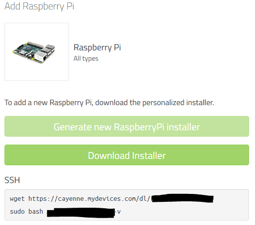
Now you have two more steps to follow. The first is to log into your Pi via SSH and then enter the wget link, so that your Pi downloads the installation script. This script is a series of numbers and letters and is unique to you, so please do not share it with others (and it’s why I have blacked out mine above). The second step is to run the script by following the second line of code above, starting with “sudo bash”.
The installation on your Pi will vary in time depending on a number of factors – i.e. internet speed, which model of Pi you are using etc. When I ran my installation, I had started with a brand new Raspbian Jessie image and it took 2 – 3 minutes on the Pi 3.
myDevices Cayenne Dashboard
When installation has completed, your Raspberry Pi should appear as online on the myDevices Cayenne Dashboard – whether this is accessed via web browser or through the app. Once at this point, it is possible to check various stats for your Pi such as:
- CPU usage
- Network activity
- RAM usage
- Storage on your SD card
It is also possible to add extra sensors to the dashboard, although at the moment only a handful are supported. However, the Community Forums are filled with requests and the developers are busy working on expanding the number of supported devices available. At the moment it is possible to use the following devices with myDevices Cayenne:
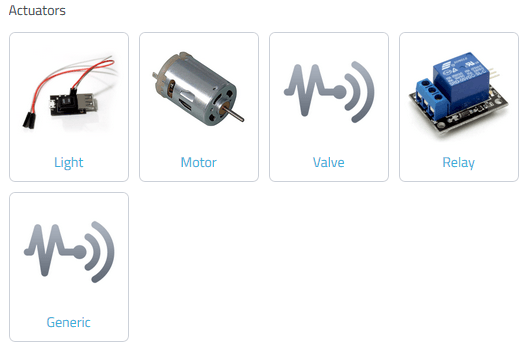
In each category, there are additional types of devices available. For example, within the Actuators -> Motor, there are two other options: Motor Switch and Servo Motor.

Likewise in the extensions category, there are a wide range of other devices under the different headers – including six analog converter devices ranging from the MCP3004 to the ADS1015.
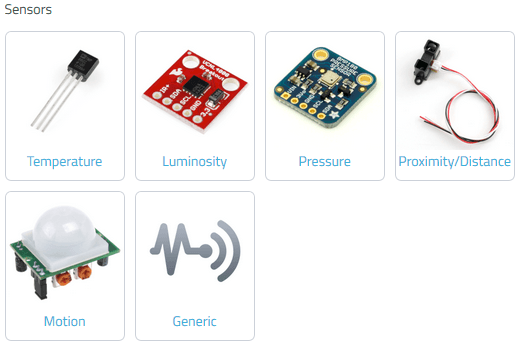
The sensors category is very appealing as these devices allow you to really explore the power of myDevices Cayenne. It is also possible to add some generic devices as either analogue or digital inputs / outputs, but this does not work for every device. For example, the DHT11 humidity and temperature sensor is currently not supported, and trying to add this manually did not work. However, the developers have acknowledged this in the forum and are actively working on an update.
Recipes, events, schedules etc.
It is worth noting that myDevices Cayenne is still in the beta phase of their project but from what I’ve seen so far, it looks very promising. For example, with some logical thinking it is possible to create events based on sensors and devices attached to your Raspberry Pi. This could be something like:

The similarities to the popular IFTTT.com are striking, and this opens a world of possibilities to Raspberry Pi users, especially as the support evolves and grows as myDevices Cayenne’s popularity increases.
Verdict – 8 out of 10
For Raspberry Pi users looking to break into the IoT world, then myDevices Cayenne is looking very promising. The simplicity of installation is refreshing, and as support grows for devices and sensors I can see this being used in various projects. Currently, the number of supported devices is quite low but as peripherals are very affordable, this is not a major issue especially for a free platform.
Once popular HATs and accessories become supported (such as Energenie’s PiMote, Raspberry Pi SenseHAT etc.), the popularity of myDevices Cayenne will surely take off. As an iPad user myself, I find it slightly disappointing that their app is not designed for iPad, but merely upscales the iPhone version. However it is just as quick to access the dashboard through Safari and add the bookmark to the iPhone as a pseudo-app instead. I for one will be keeping an eager eye on myDevices Cayenne’s progress and look forward to using it with various IoT home automation projects.
]]>
MotionEye OS is perfect for using your Raspberry Pi as a CCTV home security system. If you want to know if it detects movement when you’re out as part of a home security system, then read on…
MotionEye OS
For those of you unfamiliar with MotionEye OS, it is a dedicated operating system for CCTV systems created by Calin Crisan and distributed free via GitHub. It is very quick to set up and is perfect for your Raspberry Pi due to its lower resource requirement. Those of you who read The MagPi Magazine may recognise this guide as it was featured in their Raspberry Pi 3 launch edition in March 2016, after I originally wrote this for Pi Supply’s Maker Zone! If you want to download the PDF version of the brochure, then you can check it out here.
One benefit of MotionEye OS is its ability to detect motion and capture images and movies of what triggered it. You can even access a live stream of your camera online, even when you’re not home, which is handy if you want to check in every now and then. If you’re not home, being notified of any movement is very useful and MotionEye OS has a nifty option for custom notifications.
This guide will assume you have already set up and configured MotionEye OS and requires a Pushover licence, which costs $4.99 / £3.99. For help, check out the MotionEye OS wiki here.
What You’ll Need
- Raspberry Pi – any that work with the camera module
- MotionEye OS image (choose the right one for your Pi)
- Pushover app for iOS or Android with full license (£3.99 / $4.99 one off payment)
- Raspberry Pi Camera Module (pick from either the older 5MP or the newer 8MP versions):
Steps
1. Create an Application in Pushover
Pushover has a great, easy to use API and before we start we need to register an application with them. To do this, go click on “Register Application” under the “Your Applications” heading on their website. Give your app a name – something like RaspiMotion – and then make sure the type is “Application”. Give your app a quick description (i.e. “Push notifications sent by my Raspberry Pi”) and, if feeling creative, upload a custom icon which will show in your Pushover client app whenever a notification is sent.

2. Get you API Token and User Key
Once you have created your application, you should have access to an API Token/Key. This is a combination of numbers and letters – please keep this a secret! You’ll also need your user key, which is shown once you log in to Pushover’s website.
Okay, now you have an app and your API and user keys. You’ll now need to download (or recreate if you so wish) a simple Python script to tell your Raspberry Pi to work its magic once the script is called upon by MotionEye OS.
3. Create your Python script
MotionEye OS is not like Raspbian. You cannot use certain commands as you would normally (such as git clone), so we’ll have to create our Python script manually (or you can drag and drop using WinSCP if preferred). We also do not need to use sudo as we’re already logged in as root by default. Our script needs to live in the data folder, so let’s go there and create pushover.py using Nano:
cd /data
nano pushover.py
Then once here, you’ll need to copy and paste or type in my code, whilst also including your API Token and User Key where required.
My code can be found over at my GitHub repository, but you can also use the following here:
#!/usr/bin/python

#################################################################################
# Created by Wesley Archer (aka. Raspberry Coulis) to enable push notifications #
# via Pushover.net in MotionEyeOS. See Pushover's API FAQ for more detailed use #
# Also featured on Pi-Supply.com's Maker Zone.                                  #
#                                                                               #
# Follow me:    @RaspberryCoulis                                                #
# Visit me:     raspberrycoulis.co.uk                                           #
# Email me:     [email protected]                                    #
# Like me:  facebook.com/raspberrycoulis                                    #
#################################################################################

import httplib, urllib

conn = httplib.HTTPSConnection("api.pushover.net:443")
conn.request("POST", "/1/messages.json",
  urllib.urlencode({
    "token": "APP_TOKEN",                       # Insert app token here
    "user": "USER_TOKEN",                       # Insert user token here
    "html": "1",                                # 1 for HTML, 0 to disable
    "title": "Motion Detected!",                # Title of the message
    "message": "<b>Front Door</b> camera!",     # Content of the message
    "url": "http://IP.ADD.RE.SS",               # Link to be included in message
    "url_title": "View live stream",            # Text for the link
    "sound": "siren",                           # Define the sound played
  }), { "Content-type": "application/x-www-form-urlencoded" })
conn.getresponse()
4. Make your script executable
As with the majority of scripts used on a Raspberry Pi, we need to make sure it can be executed otherwise it is nothing more than a fancy collection of text! You can do this either from the command line, or from within WinSCP. From the command line, make sure you are in the data folder and then type:
chmod +x pushover.py
Or using WinSCP, select the pushover.py file in the data folder then press F9. In the window that appears, change the permissions to 0755 and then click “OK” to confirm.
5. Configure MotionEye OS to use your script
Now that we have our script, we need to tell MotionEye OS to use it when it detects motion. To do this, log in and then go to the “Motion Notifications” menu and then turn on “Run A Command”. You then need to specify which command to run, which will be the Python script you just created. This will be “/data/pushover.py”. Click “Apply” once done to confirm the changes.

6. Test it out!
Hopefully by now, you have created your Python script, made it executable, told MotionEye OS to use your script when it detects motion and have the Pushover app installed on your smartphone or tablet. We now need to test that it works! Wave your hand in front of your Raspberry Pi Camera (or you can do a dance if you are feeling energetic!) and then shortly afterwards, you should receive a notification via Pushover warning you that motion has been detected!

Feel free to experiment with the script to customise the message displayed and sound played in Pushover. Their API documentation is really simple to follow, so be brave and have a play!
]]>
Welcome to the first Raspberry Coulis Review! Today I’ll be here to review the Zero4U, a 4-port Pi Zero USB hub created by UUGear and whether it makes a nice accessory for your Raspberry Pi Zero.
Zero4U: A 4-port Pi Zero USB Hub by UUGear
Those lucky enough to own a Raspberry Pi Zero will know that USB connections are limited on the popular pocket-sized computer. However, the guys over at UUGear have created a fantastic little 4-port Pi Zero USB hub that provides some much needed connectivity. I first saw the Zero4U after UUGear tweeted an image and a link to their site. After I retweeted expressing my enthusiasm about the device, Shawn from UUGear dropped me a line asking if I would be interested in reviewing it for them if they sent me one. Of course, I was more than happy to oblige.

Price
At the moment, you can only buy the Zero4U 4-port Pi Zero USB hub directly from UUGear themselves. They are based in the Czech Republic but ship abroad at a reasonable price. Mine arrived within a few days, and it came well packaged and protected too. As such, you need to factor in exchange rates when purchasing the Zero4U – it currently costs 200 Kč (Czech Koruna) which is roughly £5.80 / €7.40 / $8.40 with shipping costing 125 Kč, which works out at around £3.60 / €4.60 / $5.20.
Assembly
Putting together the Zero4U is very simple – no soldering is required and it only takes a couple of minutes. The hub comes with 4 sets of screws, nuts and spacers:

Before you tighten the screws together, you’ll need to ensure that the 4 pogo pins (the brass-coloured pegs on the underside of the Zero4U) sit on the brass-coloured pads on the underside of the Pi Zero (they are labelled PP1, PP6, PP22 and PP23):

Once lined up, simply place a spacer between the Pi Zero and the Zero4U and then start gently tightening with a small Philips-head screwdriver. I recommend doing this in opposite corners rather than tightening one side then the other just to distribute any forces equally.
You should then have a fully assembled Zero4U:
Powering Up
During my test, I first tried powering my Pi Zero and Zero4U using the USB 3.0 port off my laptop. Whilst this booted and worked well, I was limited to what I could connect because there was not enough power being provided to the peripherals attached. However, when I switched to the proper Raspberry Pi PSU (providing 2A) then everything worked perfectly. Therefore the same rules apply to the Zero4U as with any USB peripheral attached to your Raspberry Pi – make sure you have a suitable power supply!

Functionality
Simply put, the Zero4U is a Pi Zero USB hub and it does the job perfectly well. There are some nice additional features, such as white status LED’s that show which ports are in use and a blue power LED. If you wanted to use the Zero4U with other Raspberry Pi’s (i.e. with existing USB ports) then you can also connect the hub via mini-USB (on the Zero4U) directly to the Raspberry Pi and add 4 more USB ports, however the current provided is slightly lower this way because it switches to bus-power mode as opposed to self-power mode. To provide more current to the USB ports if you connect to any other Pi than the Zero), then you may need to provide additional power via the JST 5V port. There are more detailed instructions available on the Zero4U product page.

Final Thoughts
As Raspberry Pi accessories go, the Zero4U is an excellent one. Not only is it well made, it is very easy to get up and running and provides 4 additional USB ports to your Pi Zero. The only downside I could think of was that you have to buy directly from UUGear, which is not a major issue but does add a little more to the cost for people living outside of the Czech Republic. However, their shipping fees are more than reasonable – in fact, comparable to some of the Raspberry Pi suppliers in the UK, which is fantastic considering you are paying for international shipping.
Review Score: 9 out of 10
]]>
Making a Raspberry Pi Audio Player is a relatively straight forward project. With its lower power consumption, small form factor and relatively inexpensive accessories, it is ideally placed for audiophiles who want to listen to crystal clear, high quality audio. However, you may well need to invest in an audio accessory to take full advantage of this.
I experimented with the Raspberry Pi as an audio player before, but was pretty unimpressed when using the default connections. I managed to improve things slightly by hooking up my Pi to my Blu-Ray surround sound system via HDMI, but this was far from ideal. I then parked this idea, until I read October 2015’s edition of The MagPi Magazine and saw a review of IQaudIO’s Pi-DAC+.
Enter the DAC
Making a Raspberry Pi audio player does not need any other accessories. However, unless you are using the HDMI port to provide audio out to a suitable receiver, then the 3.5mm jack will not offer the best quality audio. It is worth investing in a DAC, or a Digital-to-Analogue-Converter.
I’ve heard about DAC’s before – through an audiophile friend of mine as he raved about them. Personally, I never thought much of it but then I realised that my wife’s Denon Hi Fi was just sitting in a box in the garage of our new house, and now that we have the space to use this, I thought it would be worth revisiting the Raspberry Pi audio player and the raving review of IQaudIO’s Pi-DAC+ was all the persuading I needed.
The Pi-DAC+ is an excellent HAT compatible add-on specifically designed for the Raspberry Pi. I purchased mine through Pimoroni, particularly as they had their excellent Pibow Audio Case, which meant that I could house my shiny new DAC inside a purpose-made case.
Assembly
Putting everything together was simple! The Pi-DAC+ simply attaches to the Raspberry Pi’s GPIO’s and the Pibow Audio Case was equally easy to assemble. Everything fits together easily in a matter of minutes, giving me the hardware side for my Raspberry Pi Audio Player.
Which software?!
To get the most out of our Raspberry Pi Audio Player, we need to pick some software designed to maximise your listening experience. There are a few options available, but I found that MoOde, RuneAudio and Volumio were the most popular. They are all very similar – in fact, they all started under the Volumio project but their developers went their own separate ways and forked their own versions.
In essence, they are all self-contained operating systems – they all play audio, support the Pi-DAC+ and allow control of the Pi via custom user interface accessed via HTTP. Installation of each OS is the same – simply download the latest disk image then flash it to your SD card and away you go.

Pros:
- The original platform
- Nice UI
- Simple setup
Cons:
- No artwork support (at time of writing)
- Not the fastest to boot

Pros:
- Displays album artwork
- Customisable UI
- Nice library options
- Quick to boot
Cons:
- Slightly more complex to set up and configure (but has good guides)
- Updating is a manual process

Pros:
- Displays album artwork
- Customisable UI
- Nice library options
Cons:
- Not as quick as MoOde
Which one should I choose?
Well that is entirely up to you! I experimented with the different distros because setting up SD cards is relatively quick and simple! Once I was happy with a setup, I made a quick image backup using Win32 Disk Imager, wrote the new distro and popped it into my Pi. The main differences for me were around the UI and UX and at the end of the day, I went for what I liked the most.
Audio quality was superb on all the distros and I am really pleased with my setup.
]]>
This guide (which is also featured over on Cyntech’s blog) will show you how to use the Lisiparoi camera add-on to create a Raspberry Pi night vision camera using Cyntech’s very affordable Model B case.
Raspberry Pi Night Vision Camera Hack
If like me, you are an early adopter of the Raspberry Pi and have bought the new models as they are released, you probably have a surplus of older Model B’s lying about at home. It would be a crime to let them go to waste, so why not turn them into a self-enclosed Raspberry Pi Night Vision Camera? I recently bought Jason Barnett’s (also known as Boeeerb on Twitter) nifty little Lisiparoi – a light source add-on for the Raspberry Pi Camera Module (including infra-red) – and I wanted to use this as part of a home-made CCTV setup. I also had a couple of Cyntech’s Berry Black cases (for the Model B Pi) at home, and seeing as they are cheap as chips, I decided I would have a go at modding one of my cases to incorporate the Lisiparoi and Camera Module all-in-one.
For my first attempt, I am very pleased with the result. Looking at the completed project, you could never tell I hacked this case using nothing more than a pencil, a drill, my wife’s nail file (shhh) and a sharp knife!
Parts used:
For my Raspberry Pi Night Vision Camera, I used the following parts:
- Raspberry Pi Model B
- Cyntech Berry Black Case (or any other colour)
- Lisiparoi Camera Add-On (IR version for this, but works with the normal version too)
- USB WiFi Adapter
- Raspberry Pi Camera Module (No-IR used, but works with normal version)
- Suitable power supply
Time required:
30 to 60 minutes, but take your time where needed especially when using sharp tools!
Tools required:
- Drill and small drill bit (1mm or 2mm is an ideal size)
- Small file (I used a metal nail file)
- Pencil
- Sharp knife (craft or Stanley knife)
Instructions:
Making your Raspberry Pi Night Vision Camera is relatively simple, but hopefully this step-by-step guide will make it even easier:
- Place the Lisiparoi on the Berry Black case in the place you want it – make sure you allow enough room around the outside so it is not too close to the edge. Draw around the Lisiparoi with a pencil – this will be our reference point so we can work out where to start drilling and filing. Take a look at my photo for reference:

Measuring up before cutting - We will need to cut out a few points in our case – we’ll need to allow a space for the headers (so we can connect the Lisiparoi to the Raspberry Pi’s GPIOs), and a square hole for the Raspberry Pi Camera Module. We’ll also need to drill small holes for the nuts and bolts to secure the Lisiparoi to the case. All of this will involve a little trial and error, but remember – you can always cut more, but cannot put back what you’ve removed!
- Start with the mounting holes – I did this by simply placing my Lisiparoi on the case in the place I wanted it, and then carefully drilled through the case using the holes in the Lisiparoi as a template. We can refer to these holes when marking out the holes for the camera module and for the headers.
- You should now have two small holes in your Berry Black case and a pencilled outline of your Lisiparoi. We can now drill small holes for the header – if you take a look at my photo, you can see that the header holes are a few millimetres away from the bottom edge of the Lisiparoi – again start small and increase the size of the holes as you go along (if needed) – it doesn’t have to be exact, millimetre accurate hole as your Lisiparoi will hide everything once in place.
- Drill more holes to the approximate width of the Lisiparoi header, and then use a small file to square-off the hole, fine tuning it by checking with the header in place until it fits nicely.
- Now we need to cut a hole for the Raspberry Pi Night Vision Camera Module to fit through. I drew around the module (in the same way I did with the Lisiparoi) to mark the dimensions, and then drilled several holes ON THE INSIDE EDGE OF THE OUTLINE (otherwise the hole will be too big) – this will make cutting out the hole a lot easier! This is what mine looked like after I cut out all the holes.

Holes for the Camera and Lisiparoi have been cut out - I then CAREFULLY used my sharp knife to cut out the hole – it doesn’t need to be surgically neat, as we’ll file it down later.
- Once the camera module hole has been cut out, use the small file to square-off the hole again, checking that everything fits nicely.
- If you’re happy that everything fits nicely, it is now time to start assembling the case using the nuts and bolts provided, securing it to your case. If you haven’t soldered the headers onto your Lisiparoi, do this first but make sure you solder them so that they are on the inside of the case and pointing downwards so you can attach your jumper cables to your Raspberry Pi’s GPIOs once fully assembled.
- Connect all your cables, including the ribbon cable for your camera module, and then screw the lid on your case and then you’re done!
Example image
Below you can see an example of the image captured by the No-IR camera with the IR light source from the Lisiparoi.
Day

Night

As you can see, it’s not fantastic unless the object is close but with an external 12v IR LED light source, it would be great.
Software quick-start:
For the purpose of this guide, we’ll be using MotionEyeOS (formerly MotionPie) to create our Raspberry Pi Night Vision Camera, as it is very slick, purpose-built and well supported. First thing you’ll need to do is download the image file from their GitHub site but make sure you pick the one relevant to your model Pi first.
Once downloaded, write the image to your SD card (plenty of guides available for this, so won’t cover that in here) and then pop it into your Pi. Before you fire it up, make sure you have an Ethernet cable connected to your Pi first as we’ll need to connect to the Pi to enable WiFi and connect to your network.
The first boot usually takes slightly longer than normal as MotionEyeOS, but when it’s all done you will need to access the interface via your preferred web browser. By default, MotionEyeOS uses port 80 so this means you only need to enter your Pi’s IP address in your browser and you should then be presented with the login page. There are a number of ways to find your Pi’s IP address, but I prefer using a Windows-based programme called Advanced IP Scanner as this is simple and quick to use. You can download it for free from their website.
When you find yourself at the MotionEyeOS login screen, the default username is ‘admin’ and the password is blank. You can change this in the settings yourself if you wish. If you don’t see the login screen, click on the little key icon in the top-left corner.
Again, I won’t go into too much detail on the configuration here, as there is a great wiki page on their site, but in essence you will need to make sure your camera has been added and configured the Pi to use WiFi (including adding your SSID and password). You can overclock the Pi, tweak the camera resolution and much more. One big piece of advice I’d give is that once you are happy with your setup, make a backup of your settings (from within MotionEyeOS) and keep this somewhere safe. Therefore, if you need to do a reinstall, you only need to be able to login to MotionEyeOS to restore your settings from your backup. Very handy!
Once you are happy with your setup, you should have a fully-working, Raspberry Pi Night Vision camera! I connected my Lisiparoi so that when the Pi is powered, so will the Lisiparoi. However, you can add more sophisticated methods for this if you wish (i.e. via a button or GPIO control) – check out the Lisiparoi setup guide for more details on this.
]]>
Now that the Raspberry Pi 3 comes with Bluetooth and WiFi built-in, people (including me) were excited at the increased flexibility this offers. I was already thinking about using the Pi 3 in my Raspberry PiStation build so that I could do away with the extra dongles. Setting up the WiFi was straight forward – it was the same process when using USB WiFi adapters, but getting the Bluetooth module to work properly was a little more complex and I found it a little frustrating. Hopefully my guide will help you fix Raspberry Pi 3 Bluetooth issues!
Fix Raspberry Pi 3 Bluetooth Issues
There are many guides on how to get Bluetooth working on Raspberry Pi 3 already, but again I found that some crucial steps were missing in order for mine to work properly, so I have combined everything into one post here.
On the latest version of Raspbian Jessie (2016-02-26 at the time of writing), there were some additional modules that needed installing to fix Bluetooth on Raspberry Pi 3. If you are on an earlier version of Jessie, then you will more than likely need to run:
sudo apt-get update
sudo apt-get upgrade -y
sudo apt-get dist-upgrade -y
sudo apt-get install pi-bluetooth
You may then need to update the firmware used in the Bluetooth module, which is done by running the following:
sudo apt-get install bluez bluez-firmware
And then to install the user interface, which is very handy if you are running your Raspberry Pi 3 in desktop mode:
sudo apt-get install blueman
Now at this point, many guides I read stated that a quick reboot and then Bluetooth would be working and accessible through Bluetooth Manager in Menu -> Preferences -> Bluetooth Manager, but I found that whilst this was an option, selecting Bluetooth Manager did absolutely nothing.
After an hour or so of frustrated searches online, I stumbled across a page that stated “this happens because when Raspbian installs Blueman and the other Bluetooth software, it does not automatically add ordinary users to the “bluetooth” group. This group gives users permissions to access D-Bus, which Bluetooth uses for communication in Raspbian. This causes a “Permission Denied” error whenever a Bluetooth process initiated by the unprivileged user attempts to access Blueman.”
So to fix Raspberry Pi 3 Bluetooth issues, you need to run the following code in your terminal:
sudo usermod -G bluetooth -a pi
And to check this has worked, type:
cat /etc/group | grep bluetooth
If this has worked, you should now see the following:

Then after a quick reboot:
sudo reboot
You should now be greeted with the Bluetooth Manager icon on your taskbar, which means everything has worked!

And there we go – hopefully you can now access Bluetooth Manager and pair with your devices and get cracking!
]]>
With a range of Raspberry Pi’s to choose from, you can be forgiven for asking yourself “Which Raspberry Pi do I need?” especially when planning a new project. Whilst each Pi is affordable and very capable, you do not always need the latest model for your project.
Which Raspberry Pi Do I Need?
Since the Raspberry Pi was first launched in 2012, there have (to date) been 9 different models released (not including revisions, e.g. including mounting holes). These models include:
- Model A
- Model A+
- Model B
- Model B+
- Compute Module
- Model B 2
- PiZero
- Model B 3 (current at time of posting)
I won’t go into too much detail here, as there is a great article on Wikipedia which gives very detailed information on the differences between models and revisions, but with all this choice it can be a challenge deciding what model to use!
As an early adopter of the Raspberry Pi, I have owned pretty much every Model (with the exception of the A, A+ and Compute Module) but during that time I have used different Pi’s for different projects.
Below is a quick overview of the projects I personally tried on the different models of Pi and should help you answer the question, “Which Raspberry Pi Do I Need?” :
Model B:
- Home Theatre PC (HTPC) running Kodi (formerly XBMC) using both OpenELEC and OSMC (formerly Raspbmc)
- Always-on Automated Usenet Downloader running Sickbeard, Couchpotato and SABnzbd+
- Home CCTV system running MotionEye OS (formerly MotionPie)
- Retro gaming system running RetroPie / EmulationStation (including versions 1.0 and 2.0)
- Simple touchscreen online radio streamer using PyGame and Adafruit’s PiTFT Touchscreen
Model B+:
- HD Audio Player running MoOde Audio with IQaudio’s Pi-DAC+
- Always-on Automated Usenet Downloader running Sickbeard, Couchpotato and SABnzbd+ with Pimoroni’s PiGlow add-on board for a headless system monitor
- Retro gaming system running RetroPie / EmulationStation (version 2.0)
- Home CCTV system running MotionEyeOS
Model B 2:
- Always-on Automated Usenet Downloader running Sonarr, Couchpotato and NZBget with Pimoroni’s PiGlow add-on board for a headless system monitor
- Retro gaming system running RetroPie / EmulationStation (version 3.0), capable of running PlayStation One games and some N64 games.
- HTPC running Kodi (OpenELEC) – much snappier and responsive throughout
PiZero:
- IoT home automated lighting system using Energenie’s PiMote Control Board
- Hand-held retro gaming system running RetroPie / EmulationStation (version 3.0) inside a replica SNES controller (currently work in progress and based on Russell Barnes’ of The MagPi Magazine project)
Model B 3:
- Yet to decide!
- Would be ideal for a more powerful RetroPie setup, especially with the integrated Bluetooth and WiFi modules. Extra power should be interesting for the more modern retro games, such as N64, Dreamcast and PS One.
- Maybe well suited for a Raspberry Pi powered webserver / IoT set up?
As I said, this is a quick summary of the projects I have personally tried on the variety of Raspberry Pi models available. The list would be very long indeed if I included what they are actually capable of, but I would love to hear from you on what you have used your Pi for.
]]>