The post Jellyfish Can’t Swim in the Night Scape Story Experience Guide first appeared on STYLY.
]]>Experience Period: Saturday, October 18, 2025 – Tuesday, March 31, 2026
Recommended Experience Location: Shibuya area
*Available nationwide, but experiencing it in Shibuya, the anime’s setting, is especially recommended.
Experience Method: STYLY App (iOS/Android)
Ticket Price: ¥2,200 (tax included) / Some free AR experiences also available
Ticket Purchase Page (Special Website): https://styly.cc/yorukura-scape-story/
Duration: Approximately 1-2 hours (including travel)
About the STYLY App
To experience the content, you need to download the STYLY app.
Please download from each app store.
AppStore
https://apps.apple.com/jp/app/id1477168256
GooglePlay
https://play.google.com/store/apps/details?id=com.psychicvrlab.stylymr
Notes
- Data charges for app downloads and AR experiences are the customer’s responsibility
- Please note that some smartphone models may not support the experience
- Network connection is required for the experience
Please refer to the following for AR-compatible devices.
iPhone, iPad
https://www.apple.com/jp/augmented-reality/
Android
https://developers.google.com/ar/discover/supported-devices#google_play_devices
Experience Overview
In “Jellyfish Can’t Swim in the Night – Scape Story -“, you can enjoy the following two types of content.
“Jellyfish Can’t Swim in the Night – Scape Story -” Main Story
A fully-voiced story with an original 10-episode scenario
JELEE Photo Session
A feature that allows you to take original photos with JELEE members, also available during the main story experience
“Jellyfish Can’t Swim in the Night – Scape Story -” Main Story
The main story consists of two parts.
Audio Part: Part where you move while listening to audio
AR Part: Part where you experience AR at recommended locations
*AR experiences are available anywhere nationwide (no location restrictions), but experiencing it in Shibuya is especially recommended.
Please Read First
- The content size is approximately 300MB, so please be sure to follow the “Pre-download & Authentication” steps below *The main story cannot be played without performing “Pre-download & Authentication”
- Please close other apps before implementing pre-download & authentication
- Wearing earphones or headphones is strongly recommended for deep immersion in the story
Implementing Pre-download & Authentication
When you press the button, batch downloading of content will begin. Since it’s approximately 300MB, please be mindful of your device’s storage capacity and network environment.
Steps for implementing pre-download & authentication
- Tap the [Pre-download & Authentication] button
- Content download will start
- When “Authenticate” is displayed, tap the authenticate button
- When the “Authenticated” message is displayed, you’ve succeeded
- Tap the menu button at the bottom right, then tap the exit scene button

If Pre-download & Authentication Results in an Error
Tap the [Approve] link below the [Pre-download & Authentication] button to authenticate.

Experience Flow
This content is a story where you alternately enjoy a moving part where you walk while listening to audio content and an AR part where you enjoy AR content.
Audio Part
In the audio part, tap the [Listen to broadcast] button and head to the location that becomes the stage for the AR part while listening to the audio.
When the audio starts playing, tap the [Open map] button and move to the stage following the map guidance.
When the audio ends and you arrive at the stage, tap the [Move to details] button.

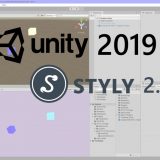
AR Part
When you arrive at the location, search for the stage background yourself while being considerate of people around you, then tap the AR start button and point your camera at the surroundings.
Audio will play, so please turn off silent mode if it’s on to enjoy the experience.

AR Port Feature Introduction
Tap the jellyfish icon to access ①Position adjustment ②Replay ③Subtitle ON/OFF settings.
①Position adjustment: Freely adjust the character’s display position
②Replay: Play from the beginning
③Subtitles: Toggle subtitle display on/off

JELEE Photo Session
“JELEE Photo Session” is a special feature exclusive to “Scape Story” that allows you to take photos with JELEE members. You can change size, position, and effects to create one-of-a-kind original photos.
*The free version can be tried from the top page of the special website.
*The free version has some character and feature restrictions.
Tap the [Launch camera] button.

You can show/hide your favorite characters (paid version allows multiple character selection), change position, change size, as well as display grids, adjust character front position, adjust lights and shadows, and customize filters.


Precautions During AR Experience
- Please be careful not to obstruct other pedestrians or vehicle traffic
- Walking while looking at your phone is dangerous, so always stop in a safe location when operating the screen
- Please be mindful of steps and obstacles around you during the experience
- Photography and experiences may be restricted in some areas such as commercial facilities or private property. Please enjoy according to local rules
When Experiencing Outside Shibuya
The main story and JELEE Photo Session are available anywhere nationwide.
All maps displayed during the experience show various spots in Shibuya, the anime’s setting.
After experiencing it near your home, we would appreciate it if you could also experience it in Shibuya when you have the opportunity.
How to Experience with XREAL AR Glasses
By connecting your smartphone or tablet to XREAL, you can enjoy the main story of “Jellyfish Can’t Swim in the Night – Scape Story -“.
*Cannot be experienced with smartphones/tablets that cannot insert Type-C cables.
Recommended Devices
XREAL Air2 Pro, XREAL ONE series
Setup Method
Launch the main story of “Jellyfish Can’t Swim in the Night – Scape Story -” and tap the AR glasses icon from the function button.
When the camera background turns black, connect your XREAL.

Recommended Usage Method
• XREAL Device Display Mode Settings
Experience through smartphone screen mirroring
*Cannot be experienced with smartphones/tablets that cannot insert Type-C cables
*Use in 0DoF state (follow mode)
*3DoF or 6DoF spatial fixed modes are not recommended
Optimal Viewing Position
Start AR playback on your smartphone/tablet screen and perform AR positioning with the “Position adjustment” button. The optimal experience is achieved when the smartphone is positioned at chest height.
Device Fixation Method
Hold the smartphone so it moves together with your body. Or fix it with a neck band-type smartphone holder.
*Fixing enables a more stable experience

Notes
Depending on the user’s usage environment, it may not display correctly.
Contact Information
Customer Support
[email protected]
The post Jellyfish Can’t Swim in the Night Scape Story Experience Guide first appeared on STYLY.
]]>The post How to set screen rotation for each scene in the STYLY mobile app first appeared on STYLY.
]]>However, depending on the experience design, you may want to lock the screen orientation to “portrait” or “landscape” for each scene.
For example, if the scene includes a UI, supporting both portrait and landscape modes requires separate UI designs and implementations, which increases production costs.
By locking the screen orientation, you can focus on designing the UI for either portrait or landscape mode only, thereby reducing production costs and effort.
How to Set Screen Orientation
Here’s how to set the screen orientation for each scene.
Open your scene in STYLY Studio.
Click the gear icon in the hierarchy menu.

Select the screen orientation you want to lock.
- Auto: Automatically switches based on the device’s orientation
- Portrait: Always displayed in portrait mode
- Landscape: Always displayed in landscape mode

By configuring this setting in STYLY Studio, you can lock the screen orientation of scenes played on the mobile app.
This setting ensures that the scene is displayed in the specified orientation (portrait or landscape) regardless of the device’s rotation lock setting.
When Locked to Portrait
The UI in the scene is always displayed in portrait mode.
Even if the user holds their smartphone horizontally, the UI will remain in portrait mode.

When Locked to Landscape
The UI in the scene is always displayed in landscape mode.
Even if the user holds their smartphone vertically, the UI will remain in landscape mode.

The post How to set screen rotation for each scene in the STYLY mobile app first appeared on STYLY.
]]>The post How to use STYLY World Canvas | How to create AR content using 3D maps first appeared on STYLY.
]]>STYLY World Canvas is a feature that automatically loads 3D map data from around the world when you place the City Anchor asset in STYLY Studio, allowing you to build precise location-based XR spaces. Based on real map data, you can place assets aligned with buildings and roads, enabling seamless integration with real cities. It supports global projects and tourism-related experiences, as well as urban XR expressions that reflect local culture and characteristics.
How to use STYLY World Canvas
When creating a new scene in STYLY Studio, select the AR template.
From the Function section in the asset selector, place “AR on City” and “City Anchor” into the scene. For how to use City Anchor, please refer to the article below.


To use the World Canvas feature, you need to place both “AR on City” and “City Anchor” assets in the scene
Once these two assets are placed in STYLY Studio, 3D map data will be loaded automatically. You can hide the 3D map data by unchecking “Show 3D Map Tiles” in the Map Mesh display at the top right.

3D map data is automatically loaded
Place assets according to the location.

Apply occlusion to buildings
You can apply occlusion to buildings by combining it with the City Occlusion asset. 

Notes
Cannot be used with city templates
City templates that can be selected when creating a new scene already contain 3D model data of the city, so they cannot be used together with STYLY World Canvas.
Locations where use is difficult
- Highly dynamic areas: In places like construction sites or temporary event venues where terrain and structures change frequently, discrepancies between map data and actual conditions may make accurate display difficult.
- Locations far from roads: Since positioning is estimated based on road data, accuracy tends to decrease in areas that are far from road networks.
- Areas with many trees or outdoor natural environments: In places where trees block the view, GPS and sensor accuracy may drop, making it difficult to determine the correct position.
- Multi-layered structures: In areas such as underpasses, underground spaces, or around buildings with multiple floors, the user’s floor level may not be correctly recognized, and content may be displayed at the wrong position.
The post How to use STYLY World Canvas | How to create AR content using 3D maps first appeared on STYLY.
]]>The post Visual Scripting: How to display date and current time with DateTime first appeared on STYLY.
]]>What is DateTime?
In Unity, DateTime is a class provided by C#’s standard library for handling date and time information. It is useful for managing time.
Preparation
- Place an empty GameObject in Unity’s scene.
- Attach “Script Machine” to it from Add Component and create a new “Script Graph”.
- Open Menu → Edit → Project Settings, select Visual Scripting, open TypeOption, and press the + button in the lower left.
- Add DateTime and TimeSpan, then press Regenerate Nodes.

Get and Display the Current Time in Console
The following nodes can be used to display the current time:
- Date Time: Get Now
- Using this, you can get the current time.
- Then, convert it to a String type and display it in the Console using Debug.Log.
Point: ToString is not necessary, but it is added to facilitate text display.

Extract Year, Hour, Minute, and Second from the Current Time
Year: Get Year

Hour: Get Hour

Minute: Get Minute

Second: Get Second

These nodes allow you to obtain individual time components.
Specify a Format for Time Display
- Add the Date Time: To String (Format) node.
- Enter the desired output format in the “Format” field. For example:
- yyyy/MM/dd H:mm:ss

You can specify the output format in the Format field.
For this example, we will use [yyyy/MM/dd H:mm:ss].
| yyyy | Year |
| MM | Month |
| dd | Day |
| H | Hour |
| mm | Minute |
| ss | Second |
The output follows the specified format. For example, if “yyyy” is changed to “yy”, 2025 will be displayed as 25.

After execution, the current time is displayed in the Console.

Shift Time from the Current Time
You can shift the time by adding Time Span to Date Time.
Required Nodes
- Add Time Span Create: Time Span (Day, Hour, Minutes, Seconds).
- For example, set it to shift the current time by 1 hour.

In this case, we shift the current time by 1 hour.

When executed, the time shifted by 1 hour is obtained.

The time was successfully shifted by 1 hour.
Conclusion
By using Visual Scripting, you can easily manipulate date and time information. The methods introduced in this article allow you to display time, customize formats, and even perform time calculations. Apply these techniques to implement timers or event scheduling in your game.
The post Visual Scripting: How to display date and current time with DateTime first appeared on STYLY.
]]>The post Create cinematic effects with Unity’s Cinemachine! How to move objects freely with Dolly Cart first appeared on STYLY.
]]>This time, we will introduce how to use CinemaScene in STYLY.
What is CinemaScene?
Cinemachine is a powerful tool in Unity that makes it easy to create cinematic camera effects. By using the “Cinemachine Virtual Camera,” you can intuitively set up various camera movements such as target tracking and smooth camera transitions.
Preparing CinemaScene
Open Unity’s menu bar and go to Window → Package Manager.

– Select Unity Registry and enter “Cinemachine” in the search bar at the top right.
– Select “Cinemachine” and install it.

Dolly Cart (Move an Object Along a Path)
Move an Object Along a Path Using Dolly Cart
- Place Dolly Track with Cart
- In the Hierarchy window, select “+” → Cinemachine → Dolly Track with Cart and place it in the scene.

2. Prepare the Object to Move
- Place a “Cube” in the scene.
- Attach the “Cinemachine Dolly Cart” component to the Cube using Add Component.
* In this tutorial, we will show how to move any object along the track. Therefore, we won’t use the Dolly Cart that was placed automatically.

3. Set the Path
- Assign the “CinemachineSmoothPath” attached to the Dolly Track to the Path field of the “Cinemachine Dolly Cart” attached to the Cube.
- Set the Speed to “1”.

Attaching the Created Path
4. Enable Looping
- Select the Dolly Track and check the “Looped” option in the “CinemachineSmoothPath” settings.

5. Test the Movement
- When you run the scene, the Cube will move along the green rail (path).

Move the Cube in a Circular Path
1. Edit the Path
- In the Dolly Track’s “CinemachineSmoothPath” Waypoints, click “+” to add more points.
- Move the newly created points (spherical markers) to form a circular path.

Modifying the Path
2. Test the Movement
When you run the scene, the Cube will move along the circular path.

Upload the scene to STYLY and check the movement.

The scene is now successfully running in STYLY.
The post Create cinematic effects with Unity’s Cinemachine! How to move objects freely with Dolly Cart first appeared on STYLY.
]]>The post Visual Scripting: How to take advantage of Custom Events first appeared on STYLY.
]]>What is Custom Event?
In Unity’s Visual Scripting, a Custom Event is a mechanism that allows you to define and call custom events at any time. It is useful for communication between scripts and triggering specific processes.
This time, we will create a system where pressing a button changes the color of an object.

We will create a Script Graph with this structure.

The completed project can be downloaded from the following:
Preparation
Place the following objects in the scene:
- Cube (the object whose color will change)
- Button × 2 (buttons labeled “Red” and “Blue”)
Arrange the objects appropriately (refer to the sample layout).
Creating ChangeColorReceiver
1. Add a “Script Machine” component to the Cube.
2. Create a new Script Graph and name it ChangeColorReceiver.
3. Create String-type variables named “Change Red” and “Change Blue”.

Add the following nodes:
- Custom Event: Set an event name and configure it to receive a String-type argument.
- Get Material: Retrieve the Cube’s material.
- Change Color: Change the material color based on the received argument.

Creating ChangeBlueGraph and ChangeRedGraph
1. Add a “Script Machine” component to each button.
2. Create the following Script Graphs for each button:
- For Red: ChangeRedGraph
- For Blue: ChangeBlueGraph
3. Create a GameObject-type variable named “ChangeColorCube” and assign the Cube to it.


Add the following nodes:
On Button Click: Starts the process when the button is clicked.
Call Custom Event: Input the String-type variable names “ChangeRed” and “ChangeBlue” from the ChangeColorReceiver creation step into the CustomEvent node (make sure to enter the spelling correctly).


Execution
Pressing the buttons will change the Cube’s color to either “red” or “blue”.
Conclusion
Custom Events are a useful mechanism in Visual Scripting that enable flexible communication between scripts. By leveraging this system, you can build simple and manageable event-driven systems.
The post Visual Scripting: How to take advantage of Custom Events first appeared on STYLY.
]]>The post STYLY for Vision Pro: How to record and playback with a microphone ,Easy implementation with Unity Visual Scripting first appeared on STYLY.
]]>Place the Microphone
1. Place a Cube in the Hierarchy for the microphone.
2. Add the following components to the Cube:
- AudioSource (Add via Add Component)
- ScriptMachine (Add via Add Component)

To enable the Visual Scripting nodes used in this tutorial, open Edit → Project Settings.

Open TypeOptions under the Visual Scripting tab.

Scroll to the bottom, press the + button, and add a new option.

Add Microphone.

Press Regenerate Nodes to rebuild the options.

Preparing for Recording
1. Create a new ScriptGraph in ScriptMachine.
- Example: “Voice Recorder”
2. Add the following variable to ObjectVariable:
- Name: AudioSource
- Type: “AudioSource”

3. Assign the AudioSource from the Cube in the Hierarchy to the AudioSource variable by dragging and dropping.

4. Add the following components to the Cube:
- XR Grab Interactable
- XR Poke Filter
- Add settings to the Interactable Filter in XR Grab Interactable’s Hover option.
- For more details, refer to STYLY for Vision Pro: How to Easily Implement Button Operations with the Poke Feature.

Building the ScriptGraph
Add and connect the following nodes:
Access Vision Pro’s Microphone
- Use GetDevices and FirstItem nodes to get Vision Pro’s microphone.
- Assign the microphone name to the Device Name field in the Start node.
- Settings for the Start node:
- Length Sec: Recording duration (e.g., 5 seconds)
- Frequency: Sampling rate (e.g., 44100Hz)

Setting Recording Conditions
- Use GetPosition to get the volume level.
- Add a condition to skip recording if the volume is 0 or lower (i.e., no sound is detected).

Visual Feedback During Recording
- Create a new Material and attach it to the Cube.
- Use SetColor to indicate recording and playback states:
- Recording: Red
- Playback: Blue

Implementing Recording and Playback
Add and connect the following nodes:
- Use a Timer node to manage the recording time (5 seconds).
- Use an End node to stop recording.
- Use a Play node to play the recorded audio.

Node 1: xxxxx

Node 2: Full Graph
Run
You can now successfully record and play back audio.

Watch with audio here:
The post STYLY for Vision Pro: How to record and playback with a microphone ,Easy implementation with Unity Visual Scripting first appeared on STYLY.
]]>The post STYLY Modifier Manual first appeared on STYLY.
]]>First, in the overview section, we will cover everything from understanding the overall concept of modifiers to explaining their specific functions.
Overview
Modifiers are functions in STYLY Studio that allow you to add effects such as “animation” or “interaction” to assets.
These effects themselves are referred to as “Modifiers”.
Previously, adding such features in STYLY required the use of Unity or PlayMaker, but now anyone can easily add them without coding.
Modifiers added in STYLY Studio are compatible with the devices listed in the Modifier Operation Environment Table below. It is now easy to create effective scenes in VR/AR.

Modifier function usage image
Modifier Operation Environment List
|
Layer |
Device |
Distribution App |
|
VR |
PCVR |
Steam |
|
VR |
Standalone VR |
Quest2 |
|
VR |
Mobile |
Android/iPhone/ |
|
AR |
Mobile |
Android/iPhone/ |
|
Web |
Web Browser |
Web Player |
Download List

Modifier Introduction
Here are some of the modifiers available in STYLY Studio.
Interaction
Interaction allows you to add modifiers that are useful when creating interactive works such as games.
Example: Make equippable

You can equip assets to the controller.
Style change
Style change allows you to alter the appearance of assets.
However, depending on the shape and other factors, the result may not appear as expected. (Texture mapping follows the object’s UV.)
Example: Stars

Appearance changed to a star pattern
Animation
You can add motion such as rotation or movement to assets.
Example: Rotate

The object rotates
Humanoid Animation
Humanoid Animation is for models that support Unity’s humanoid animation format “Humanoid”.
You can apply animations to humanoid assets uploaded to STYLY Studio (*To use them, convert your asset to humanoid in Unity, create a prefab, and then upload it to STYLY).
Example: Breakdance Motion
 Breakdance motion is applied.
STYLY is a platform where even non-engineer, non-programmer artists can easily create and publish VR/AR works.
For example,
“I can use Blender, but not Unity…”
“I don’t know how to program in Unity”
“I only know how to use Adobe software”
—even artists and creators like this can easily create animated and interactive works.
You can also upload and use 3D models made in 3DCG software like Blender, image files such as JPG/PNG, and video files like .mp4.
Refer to the following article for how to upload.
Add modifiers to your uploaded assets and create your own unique VR/AR work!
Practical Section
In the practical section, you’ll learn how to actually use modifiers and try creating a simple scene.
You need to create an account in advance to use STYLY Studio.
Refer to the following article to create an account.

Access STYLY Studio
Let’s access STYLY Studio.
https://gallery.styly.cc/studio
Or,click the STUDIO button at the top right of the STYLY Gallery page.
 STUDIO
Access STYLY Studio and select “Create Scene”.
 New Scene
If you want to create an AR scene, select AR Scene Template; if you want to create a VR scene, select VR Scene Template.

Template
This time, we’ll select the VR Scene Template to create a VR scene.
Once you select a template, the scene will be displayed on the screen as shown below.

Scene
You’re now ready to go.
Try using Modifiers
Let’s actually place an asset in the scene and get used to using Modifiers.
First, add an asset.
Click the “Asset button” in the top left menu bar.
[caption id="attachment_57520" align="aligncenter" width="1000"] Asset button
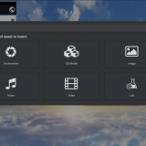
The asset menu will appear. Select “3D Model” → “Model”.

3D object

Model
Choose any 3D model you like.
This article uses “Leather Sofa Wine Red”.

Search for Leather Sofa Wine Red
Once you select the 3D model, it will be placed in the scene.

The sofa is placed
When you select the model, it will be highlighted.

Sofa
In that state, click the Modifier icon.

Modifier icon
A list of modifiers will appear.

Modifier list
Scroll to view various modifiers.
You can also use the search bar labeled “search…” at the top.
Use this when searching for specific modifiers.
This time, we’ll add the “Rotate” animation modifier to the sofa.
Type “Rotate” into the search bar to find the animation modifier.

Rotate
Click [Animation] Rotate.
The sofa object will start rotating.
Additionally, a modifier settings panel will appear below the object icon.

Rotating
Modifier List
Modifiers offer a variety of effects.
You can even create simple game-like scenes without any coding. Be sure to try out different options!
Interaction
You can equip objects to the controller, make them grabbable, or enable object destruction.
[Interaction] Make equippable
You can equip an object to the controller.

You can equip an object to the controller
[Interaction] Make draggable
Allows you to grab and move the object.

Allows you to grab and move the object
[Interaction] Make breaker / Breakable
When a Breaker object collides with a Breakable object, it destroys the Breakable object.

When a Breaker object collides with a Breakable object, it destroys the Breakable object
Style Change
You can change the appearance of objects.
However, depending on the shape, it may not look as expected. (Texture mapping follows the UVs of the object.)
[Style Change] Stars
Changes the appearance to a star pattern

Star pattern
Star color: Change the color of the stars
Background color: Change the background color
Number of stars: Change the number of stars per row and column
[Style Change] Rim light
Changes the appearance to a glowing rim light effect

Rim light
Light Color: Change the light color
Intensity: Adjust the light intensity
[Style Change] Gradient Color
Changes the appearance to a gradient color

Gradient Color
Start color: Set the starting color
End color: Set the ending color
[Style Change] Dots
Changes the appearance to a polka dot pattern

Polka dots
Dot Color: Change the dot color
Background Color: Change the background color
Number of dots: Change the number of dots per row and column
[Style Change] Change Color
Changes the overall color of the appearance

Change color
Color: Change the overall appearance color
[Style Change] Checker board
Changes the appearance to a checkerboard pattern

Checkerboard
Color 1: Change the color of one set of squares
Color 2: Change the color of the other set of squares
Number of squares: Change the number of squares per row
[Style Change] Wood
Changes the appearance to a wood grain pattern

Wood grain
[Style Change] Rock
Changes the appearance to a rocky texture

Rock
[Style Change] Marble
Change the appearance to marble

Marble
[Style Change] Lava
Change the appearance to lava

Lava
Animation
You can add movement such as rotation and translation to objects.
[Animation] Rotate
Rotate the object

Rotate the object
Angular Velocity X: Change rotation speed on X-axis
Angular Velocity Y: Change rotation speed on Y-axis
Angular Velocity Z: Change rotation speed on Z-axis
[Animation] Heartbeat
Make the object expand and contract in a steady rhythm

Expand and contract in rhythm
Beat Duration: Rhythm interval
Hold Duration: Time of size transition
Amplitude: Magnitude of expansion and contraction
[Animation] Orbit
Make the object rotate in a circular orbit

Circular orbit
Radius: Change the orbit diameter
Angle Velocity X: Rotation speed on X-axis
Angle Velocity Y: Rotation speed on Y-axis
Angle Velocity Z: Rotation speed on Z-axis
[Animation] Go and back
Add animation to move back and forth between initial position and a relative destination

Back and forth animation
Destination X: Change X coordinate of destination
Destination Y: Change Y coordinate of destination
Destination Z: Change Z coordinate of destination
Trip time: Change one-way travel time
[Animation] Move straight
Add animation to move in a specified direction at a constant speed

Move in a direction at constant speed
Velocity X: Change speed on X-axis
Velocity Y: Change speed on Y-axis
Velocity Z: Change speed on Z-axis
[Animation] Go and back like spiral
Add animation to follow a spiral path

Spiral path
Velocity X: Speed along spiral X-axis
Velocity Y: Speed along spiral Y-axis
Velocity Z: Speed along spiral Z-axis
Trip time: Time to reach destination
Radius: Change the spiral radius
Orbit angular velocity: Change spiral rotation speed
[Animation] Go and back like waves
Add animation that follows a wavy up-and-down path

Wave motion
Velocity X: Movement speed on X-axis
Velocity Y: Movement speed on Y-axis
Velocity Z: Movement speed on Z-axis
Trip time: Time to reach destination
Wave height: Change height of the wave motion
Wave period: Change speed of the wave oscillation
[Animation] Move to loop
Add animation that repeatedly moves the object in a straight line relative to its initial position

Looping linear motion
Destination X: Change X coordinate of destination
Destination Y: Change Y coordinate of destination
Destination Z: Change Z coordinate of destination
Duration: Time to reach the destination
Humanoid Animation
Humanoid Animation supports models using Unity’s Humanoid animation format.
To use it, set the model as Humanoid in Unity, prefab it, and upload to STYLY.

Humanoid Animation
[Humanoid Animation] Breakdancing Motion
Add a breakdancing animation

Breakdancing animation
[Humanoid Animation] Standing
Add an animation of a standing pose

Standing animation
[Humanoid Animation] Sitting Laughing
Add an animation of sitting and laughing

Sitting and laughing animation
[Humanoid Animation] Rumba dancing
Add a rumba dance animation

Rumba dance animation
The post STYLY Modifier Manual first appeared on STYLY.
]]>The post Manual for Creating AR Cityscapes of Major Cities in Japan first appeared on STYLY.
]]>We will show you how to create, distribute, and experience these AR scenes in Tokyo, Osaka, Nagoya, Sapporo, Fukuoka, Kyoto,Kanazawa, Hiroshima and Niigata.
How to Create AR Cityscapes
Select a City Template
Access STYLY Studio to get started.
A STYLY account is required, so if you do not have an account, go to https://gallery.styly.cc/signup to sign up.
Log into STYLY Studio and click the “CREATE SCENE” button. Then, a list of templates will be displayed.

Click “NEW SCENE”
Select a city template.
Enter a title for your scene and click “CREATE”.
List of available city templates:
- Sapporo Odori Park (Hokkaido)
- Tokyo Shinjuku West Exit (Tokyo)
- Tokyo Shibuya Station (Tokyo)
- Niigata Furumachi (Niigata)
- Niigata Bandaijima (Niigata)
- Kanazawa Station (Ishikawa)
- Nagoya Station (Aichi)
- Kyoto Station (Kyoto)
- Osaka Shibatamachi (Osaka)
- Osaka Dotonbori (Osaka)
- Osaka Castle (Osaka)
- Hiroshima Station (Hiroshima)
- Fukuoka Tenjin Station (Fukuoka)

Select the city template
Using city templates to create AR scenes linked to the real world
In STYLY, you can create AR scenes using the default assets such as 3D models and effects.
You can also upload your own 3D models, images and videos to create scenes with more originality.
For more information on how to use assets provided in STYLY Studio and how to upload your own assets, read the following article:
How to import scenes and prefabs from Unity:
How to add animation to an asset using Modifiers:
Now, let’s place the assets in STYLY Studio.
We recommend putting them on the roof or walls of a building.

If you’re not sure where to place the assets, try putting them on the roof or walls of a building.
Realistic scale 3D city models
The 3D city models are the same size as real world buildings.
The assets will be placed in the same location in the real world as they are positioned in STYLY Studio.

The size of the 3D city models and real world buildings are the same
3D city models are not displayed during the AR experience
The 3D city models will not be displayed in the AR experience, as they are only used as a guide for building your scene.

STYLY Studio’s 3D city models will not be shown during the AR experience
Preview your scene with Your Position
Your Position allows you to view the scene from the viewer’s perspective.
Click “reset position” at the right of STYLY Studio to view the AR scene from Your Position’s perspective.
When building a scene, you will be inspecting it from various angles and heights, so it may start lacking the viewer’s ground level perspective. Go back and forth in multiple views to make sure your scene turns out exactly how you expect it to be.

The scene from Your Position’s perspective
Experience the AR scene anywhere from designated areas
To experience AR scenes using a city template, you must go to the actual city’s location.
For the exact areas of each city, see paragraph “Be at the actual city location before launching the scene”.
Using Scenes and Prefabs from Unity
Read how to upload your Unity scenes and prefabs to STYLY Studio below:
Points to note when creating AR Cityscapes
Do not delete city assets
When creating scenes using a city template, three assets are placed in the scene: the AR on City asset, the 3D city model, and the 3D city anchor.
Do not delete these three assets. If you delete them, the scene will not work as expected.
Assets that should not be deleted:
・AR on City asset
・3D City Model
・3D City Anchor

In the case of this scene, do not delete the AR on City, Tokyo Shibuya Station, and Tokyo Shibuya Station Anchor assets
How to restore city assets if you accidentally delete them
If you accidentally delete a city asset, open the Asset Selector and select the asset from Function.
You can add AR on City, the 3D city model and 3D city anchor assets from here.
If you delete the AR on City asset, add the AR on City asset to your scene.
If you delete a 3D city model, add the 3D city model that was originally in your scene.
If you delete a 3D city anchor, add the 3D city anchor that was originally in your scene.
The 3D city model and the 3D city anchor must be the same location.
If you are using the 3D city model of Tokyo Shibuya Station, make sure to match it with the Tokyo Shibuya Station Anchor.

Do not place a Skybox in your scene
When using XR Cityscape Assets, do not place a Skybox in the same scene. That applies to all Skyboxes in the Environment asset page.
If you place a Skybox in a scene, the scene will automatically switch to VR mode and you will not be able to see the environment in AR.

When using a city template, do not place a Skybox in your scene.
Do not use with the AR on Sky asset
A city template and the AR on Sky asset cannot be used together.
For more information on how to use AR on Sky, refer to the following article:
How to experience the AR Cityscape Scene
Download and Install the STYLY Mobile App
Download STYLY for iOS
https://apps.apple.com/jp/app/id1477168256
Download STYLY for Android
https://play.google.com/store/apps/details?id=com.psychicvrlab.stylymr
Devices supporting AR Cityscapes
https://developers.google.com/ar/devices
AR Cityscapes will only work on devices supporting Depth API.
1. Launch the STYLY mobile app and tap on My Page.
2. Tap the “Log In” button to log in.
3. A list of the scenes you have created will be shown, so tap the AR scene you would like to experience.
4. Tap the Download button to download the scene in advance.

My Page > Log In > Tap on the AR Cityscape scene > Download (Update)
Be at the actual city location before launching the scene
Make sure to be at the location of your city template before launching your scene.
For example, to experience an AR scene using the Tokyo Shibuya Station template, you will need to be in front of Shibuya Station in Tokyo.
To see the areas available for creating AR cityscapes, refer to the maps below:
AR Cityscapes Supported Areas
Sapporo Odori Park
Tokyo Shibuya Station
Nagoya Station
Kyoto Station
Osaka Dotonbori
Fukuoka Tenjin Station
Niigata Furumachi
When you arrive at the location, launch the STYLY mobile app and tap the “Play” button.

Tap “Play” after arriving at the location
Point your camera to the surrounding buildings for the app to recognize your current location. Now you can experience the AR scene in the city!

Point the camera to the top of surrounding buildings to experience the AR scene!
Start the scene on ground level
Make sure to be on ground level when you start the AR scene.
Launching an AR scene on the second floor or above or on a bridge will result in misalignment.
For questions about STYLY, bug reports, and improvement requests, please contact the STYLY FORUM: https://en.forum.styly.cc/support/discussions
For business inquiries, contact us from the link below:
https://styly.cc/contact
Cautions
It will not work properly under the following circumstances
- Roofed areas
- Indoor, arcade shopping street, underground, etc.
- Dark places
- At night and in areas with low outdoor lighting (the Shibuya Scramble Crossing is an exception because it is very bright even at night).
- Near the water’s edge
- Places with water surface reflections such as rivers, ponds, lakes, and oceans
The post Manual for Creating AR Cityscapes of Major Cities in Japan first appeared on STYLY.
]]>The post Article describing the JACKSON kaki’s scene using the Modifier feature first appeared on STYLY.
]]>I introduce the appreciation points of the scene, how he uses Modifier, and how he arranges Modifier.
About JACKSON kaki

JACKSON kaki (real name: Takaumi Arakaki) is an artist/creator who creates multi-media works such as VR/AR/MR, video, game, installation, sound art, and DJ, mainly 3DCG.
Focusing on “dimension” and “existence”, he finds the relationship between virtual space and real space in the post-Internet society.
In Japan
P.O.N.D. (PARCO MUSEUM. 2020)
AWSM ( HASSYADAI, 2020)
Yurakucho Wall Art Gallery (IDEA , 2021)
BUG4ASS ( THE PLUG, 2021)
International
DIO’ C’ E ( UltraStudio, Pescara, Italia 2020 )
Spring Attitude Festival ( EUR SOCIAL PARK, ROMA, Italia 2021 )
ARCHIVIO CONTEMPORANEO(TUBE,ROMA, Italia 2021)
(Quoted from NEWVIEW official website
https://newview.design/en/works/swiming-in-the-river )
Twitter : https://twitter.com/Kakiaraara
Instagram : https://www.instagram.com/kakiaraara
About “KANKEISEI”
This is an AR work.
I recommend that you experience it in a large space.
When you launch the work, you will see a combination of objects with motifs of human faces and bodies, and abstract structures.

In addition, the collapsed human face object moves in the space with physical expression.

The one that stands out the most is the collapsed figure dancing in the center.
The monstrous standing figure is distinctive.

This work uses the human body as a motif and depicts how it becomes an object with physical expression and animation.

Points where he uses Modifier
You can actually copy a scene on STYLY Studio and check it against the following explanations.
How to copy a scene on STYLY Studio
- First, please login to STYLY Gallery.

Select LOGIN in the upper right corner of the STYLY Gallery screen if you don’t login to STYLY Gallery.

Enter your email address and password and select LOGIN.

You are logged in. (Your icon will be displayed)
- Click on the Copy button below. *You must be logged in to copy to your account.

- When the scene is added to the scene list on STYLY Studio, you finished copying.

Copied scene is added
Explanation
This section explains what modifiers are used in STYLY Studio.
A face object called Thisperson2 has Humanoid Animation added to it.
![[Humanoid Animation] Standing is used.](proxy.php?url=https://styly.cc/wp-content/uploads/2022/03/2-5.gif)
[Humanoid Animation] Standing is used.
This face object has a humanoid bone attached to it in Blender, and then it has been made into a Humanoid in Unity and uploaded to STYLY.
By adding the Humanoid Animation Modifier, animation is applied to the face object.
Similarly, the humanoid object moving in the center also includes Humanoid Animation.
![[Humanoid Animation] Rumba dancing and Breakdancing Motion are used.](proxy.php?url=https://styly.cc/wp-content/uploads/2022/03/3-5.gif)
[Humanoid Animation] Rumba dancing and Breakdancing Motion are used.e
There are several types of Humanoid Animation. By changing the content of the animation, you can make the object move in a different way.
The Face2 object includes the Rotate Animation to rotate the object.
![[Animation] Rotate is used.](proxy.php?url=https://styly.cc/wp-content/uploads/2022/03/4-2.gif)
[Animation] Rotate is used.
You can apply Animation to any object.
You can easily move the object you have uploaded.
Animation is also used for other objects.
Face1 includes Animation’s Heartbeat.
![[Animation] Heartbeat is used.](proxy.php?url=https://styly.cc/wp-content/uploads/2022/03/5-4.gif)
[Animation] Heartbeat is used.
With Heartbeat, you can apply an animation that changes in size at a constant rhythm.
The “red objects” in this scene are all colored red by the Change Color of Modifier’s Style Change.
![He colors the objects red by using [Style change]Change Color](proxy.php?url=https://styly.cc/wp-content/uploads/2022/03/6-2.png)
He colors the objects red by using [Style change]Change Color
The three-dimensional object Abstract2 is not only turned red by Change Color, but is also includes Make Draggable of Interaction.
![You can use the controller to operate objects with [Interaction]Make Draggable.](proxy.php?url=https://styly.cc/wp-content/uploads/2022/03/7-2.png)
You can use the controller to operate objects with [Interaction]Make Draggable.
Make Draggable allows you to move the object with the controller when experiencing the scene.
As in Abstract2, two or more Modifiers can be applied at the same time.
However, if the number of Modifiers becomes too large, it may be difficult to manage the scene, and some Modifiers may conflict with each other, such as animation, resulting in unintended operation.
This is an explanation of the “KANKEISEI” scene using Modifier feature.
How to experience a AR scene
If you are accessing this page from a smartphone, please click on the “Experience the Scene” button (*If you are experiencing the scene on a smartphone for the first time, please also refer to the following instructions).
After clicking, the following screen will be displayed.
If you have already downloaded the STYLY Mobile app, please select “Continue on Browser”.

You can then select “Play on Mobile App” to experience the scene.

If you are accessing this page from a PC (web browser), you can experience the scene by clicking the “Experience the Scene” button, selecting the Mobile icon on the scene page, and scanning the QR code.

Download the STYLY Mobile app


For those who want to know more about how to experience the scene
For more information on how to experience AR scenes, please refer to the following article.
![[Summary] How to experience STYLY scenes VR/AR(Mobile) / Web Browser Introduction by step](https://styly.cc/wp-content/uploads/2020/04/スクリーンショット-2020-04-10-12.53.04-160x160.png)
The post Article describing the JACKSON kaki’s scene using the Modifier feature first appeared on STYLY.
]]>The post Unity Plugin for STYLY How to resolve the error when uploading first appeared on STYLY.
]]>If you encounter an error while trying to upload a Unity asset, please refer to this guide.

STYLY Plugin for Unity Error
What is Unity Plugin for STYLY?
STYLY allows you to upload prefabs and scenes created in Unity.
The plugin used for this process is called “Unity Plugin for STYLY.”
Refer to the following article for instructions on how to upload:
Why STYLY Upload Takes Time
The role of Unity Plugin for STYLY is not just to upload prefabs and scenes to STYLY.
It also processes them for multi-platform compatibility.
Without this processing, uploaded assets will not function correctly in STYLY.
Although the upload process takes time, it is optimized to ensure a seamless XR experience for as many users as possible.
Preliminary Checks
Is Your Unity Version STYLY-Compatible?
Check the supported versions for STYLY Plugin for Unity here:
STYLY Plugin for Unity DOWNLOAD
Uploading will not work unless you use a compatible plugin version.
Are Required Modules Installed?
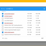
To use STYLY Plugin for Unity, certain modules must be installed in Unity beforehand.
If these modules are missing, you will see an error in the settings window like the one below.

Missing Module Error
Install the necessary modules and try uploading again.
Check the required modules at the following link:
Instructions for adding modules can be found in this article:
API Key / Email Authentication Error
If the following dialog appears during upload, an authentication error has occurred.

Authentication Error
In such cases, review the Email and API Key settings in the Asset Uploader Settings.

Check Email and API Key
Not Connected to an Account

STYLY Account Not Connected
The STYLY Plugin for Unity requires a connection to an account.
If not connected, the following error will appear:
“〇〇 (Prefab name): You don’t have an account settings. [STYLY/Asset Uploader Settings]”
Connect your STYLY Plugin for Unity to your account before uploading.
Refer to this article for connection instructions:
Scripts Are Not Supported
The programming language used in Unity, C#, is not supported in STYLY.
Therefore, prefabs or scenes containing C# scripts will not function in STYLY.
To implement object control or interaction in STYLY, use “PlayMaker.”
Learn more about PlayMaker here:
![[Unity Tutorial] Creating a Game Using Playmaker ① From Basic Introduction to Installing](https://styly.cc/wp-content/uploads/2019/06/1200px-160x160.jpg)
Unity Upload File Size Limit
As of November 2021, STYLY recommends keeping uploaded prefabs under 20MB and scenes under 100MB.
For the latest file size limitations, refer to this page:
If the file size exceeds these limits, performance may degrade, or uploads may take longer.
To reduce asset file size, check this guide:
STYLY Storage Limit
When uploading prefabs or scenes from Unity, note that STYLY has a total storage limit.
STYLY allows up to approximately 1.7GB of assets in a scene.
If this limit is exceeded, additional assets cannot be placed in the scene.
When this happens, the following error appears:

Storage Limit Error
If this message appears, you will need to reconfigure your scene.
Additionally, large file sizes may slow down scene interactions.
Manage asset sizes carefully when creating in Unity.
If you encounter an Out of Memory error preventing STYLY Studio from opening, refer to this guide:
How to Reduce Unity Upload Time
To shorten upload time, refer to this article:
Optimize your workflow for efficiency!
The post Unity Plugin for STYLY How to resolve the error when uploading first appeared on STYLY.
]]>The post [STYLY Modifier] How to Use the Style Change modifier first appeared on STYLY.
]]>Read more about STYLY Modifiers, including the Style Change Modifier, in this article:
Changing Appearances
Style Change Modifier allows you to change the appearance of an object; however, that object may not turn out as you might expect due to its shape or other factors (for example, the texture will be based on the object’s UV map).
New Style Content
We have added 44 new Style Change Modifiers to STYLY Studio, including wood, stone, glass, magma, crystal, and animated, liquid-like textures. Below, we introduce some of these basic Style Change Modifiers.
[Style Change] Crystal Clear
This Modifier makes an object look like a clear crystal and includes some animation.

Crystal Clear
Under [Style Change] Crystal Clear, use “Color” to change the color of an object.
[Style Change] Crystal Anim Frozen
This Modifier adds crystal-like animation to an object.

Crystal Anim Frozen
Under [Style Change] Crystal Anim Frozen, use “Color” to change the color of an object.
[Style Change] Liquid Anim Water
This Modifier adds liquid-like animation to an object.

Liquid Anim Water
Under [Style Change] Liquid Anim Water, use “Color” to change the color of an object.
[Style Change] Glass Gravel
This Modifier makes an object look like glass, but be careful: avoid creating objects that cover the entire screen or are extremely large, as Glass gravel, Glass sand, and Glass offset can make the scene very slow.

Glass Gravel
Under [Style Change] Glass Gravel, use “Color” to change the color of an object.
[Style Change] Grass Summer
This Modifier makes an object look like a summer meadow.

Grass Summer
The “Tilling scale” controls the pattern repeat: the higher the number, the smaller the pattern.
[Style Change] Grass Winter
This Modifier makes an object look like a meadow covered with snow.

Grass Winter
[Style Change] Wood Maple, Flat
This Modifier gives an object a woodgrain pattern.

Wood Maple, Flat
The “Tilling scale” controls the pattern repeat: the higher the number, the smaller the pattern.
[Style Change] Wood Maple Tile, Aged
This modifier gives an object a tiled, woodgrain pattern.

Wood Maple Tile, Aged
The “Tilling scale” controls the pattern repeat: the higher the number, the smaller the pattern.
[Style Change] Marble Gray Tile
This modifier gives an object a tiled, marbled pattern.

Marble Gray Tile
The “Tilling scale” controls the pattern repeat: the higher the number, the smaller the pattern.
[Style Change] Marble White Offset
This modifier gives an object a displaced, tiled, marbled pattern.

Marble White Offset
The “Tilling scale” controls the pattern repeat: the higher the number, the smaller the pattern.
[Style Change] Plaster Gray
This Modifier makes an object look like plaster.

Plaster Gray
The “Tilling scale” controls the pattern repeat: the higher the number, the smaller the pattern.
[Style Change] Fire Rock Anim
This Modifier adds magma-like animation to an object.

Fire Rock Anim
Sample Scene
In the scene below, you can view all of the Style Change Modifiers currently available in STYLY Studio. In virtual reality (VR) mode, objects can be dragged and held by hand to see even more detail.
The post [STYLY Modifier] How to Use the Style Change modifier first appeared on STYLY.
]]>The post Template scene/asset guide using Light Probe first appeared on STYLY.
]]>This feature allows you to set up more realistic and lightweight spatial lighting textures for VR and AR.
STYLY Release Note:STYLY-VR v2.9.2 (2021/12/21)
Template scenes and assets that already have the “Light Probe” feature implemented can now be used in Studio.
The template scene includes Reflection Probe and LightMap in addition to the Light Probe features, so you can create a scene with well-lit.
In this section, I will explain how to use the template scene in STYLY Studio, as well as the features of the Light Probe and other lighting settings.
List of template scenes
Dim Museum
In this template, objects are displayed in a marble-based set with natural lighting. There is also a space for setting captions in the back, which can convey the world view of the exhibition after the viewers concentrate on the works.

Template scene “Dim Museum”
Crypt Light
This template allows you to select your own images from custom assets to display on the wall. The European-style pillars, ceiling lights, and shadow textures are smooth, and the scene allows the viewer to concentrate on the work.

Template scene “Crypt Light”
Crypt Dark
This is a dark version of the Crypt Light template. You can choose between Light and Dark scenes to match the mood of your work. You can enhance the sense of immersion by using Narration and BGM.

Template scene “Crypt Dark”
What is the “Light Probe” that became available in this update?
Light Probe is a setting that simulates the lighting in the scene space for each section in advance, and stores the information about the lighting in the scene. Originally, Unity and STYLY are set to simulate lights in real time, but due to the load, the simulation is limited.

The lighting information is stored in advance for each section of the scene.
Let’s compare the scene without Light Probe setting and the scene with setting in the image.
By setting up the Light Probe, the lighting information of the space can be stored and set up without placing lights that are burdensome to the simulation such as Point Light.
This is a scene without Light Probe. Objects do not blend well with the background in areas not directly illuminated by the directional light.

Scene without Light Probe
This is a scene with the Light Probe set. Even in a shaded area, the lighting of the object and the background match each other naturally.

Scene with Light Probe
Specifically, the following characteristics are reflected.
- The accuracy of lighting such as indirect light has been improved, resulting in a more natural appearance.
- Light is simulated in advance, making the scene lighter.
- When using Unity, the degree of shadow detail and the rendering range can be adjusted.
Other lighting features set up in the template scene
LightMap
A “LightMap” is also set in the template scene.
LightMap is a feature that maps and stores the light shining on an object onto the object’s texture in advance. This is especially applicable to backgrounds such as walls and ceilings. It also simulates the light hitting the object beforehand, making the scene lighter and the objects look more natural.
The following is a scene without LightMap. If you don’t place point lights in the shaded areas, there will be dark areas. However, it is difficult to set up a point light that illuminates the entire scene naturally and does not make the scene heavy.

Scene without LightMap
The following is a scene with LightMap set up. The settings for the textures in the room being illuminated are saved in the textures themselves, so the scene is rendered in a lightweight and natural light.

Scene with LightMap
Reflection Probe
In addition, a feature called “Reflection Probe” has been pre-set in the template scene. As the name suggests, this feature allows you to get a simulation of the reflected light. It can be used to show the specular reflection of metal, marble, etc. in a beautiful way.
The following is a scene without Reflection Probe set. Without setting the material and shader, the reflection will look unnatural.

Scene without Reflection Probe
The following is a scene with the Reflection Probe set. The surrounding objects are reflected naturally in the central specular object. Also, depending on the type of shader, the scene can easily be made lighter than simulating with shaders at any time, so you can expect to save weight when placing multiple objects.

Scene with Reflection Probe
How to use the template scene and assets
Let’s try using a template scene that already has the above features implemented.
This time, a “sample scene” with objects already placed in the template scene is also prepared, and you can use it from there.
How to use a template scene
Template scenes can be used from STYLY Studio.
If you are new to STYLY Studio, please refer to the STYLY Started Guide here.
To use a template scene, create a scene in STYLY Studio and open “Assets” indicated by the red frame in the upper left corner.

Select “Assets” in STYLY Studio.
Click on “3D object” under Asset, then Then select “Featured”.

3D object

Featured
Open Featured to see the template scene we will be using is available.
Let’s start by explaining how to use the DimMuseum Set. Select “DimMuseum Set”.

DimMuseum Set
If you open the DimMuseum Set, you will find the following templates. Select “DimMuseum_room_sclupter”.

Select “DimMuseum_room_sclupter”
Select “DimMuseum_room_sclupter” and it will look like this.
In this case, we have already set up the lighting for the scene, so select the “Directional Light” icon and turn it off.
This will open the template.

Turning off the “Directional Light
The next step is to actually place the objects in the template scene.
This time, we will place a custom asset from STYLY Studio.
As before, click on “3D object” and continue Select “Primitive”.
3D object

Primitive
Select “Change Texture Sphere” and place it.
This time, I added the STYLY logo in the “Please upload an Image File” field.
To see how the specular reflection looks, I set the “Metalic” and “Smoothness” values to 1.
Once the settings are made, select the blue “ADD TO SCENE” button and place it on the pedestal.

Change Texture Sphere

This time, we will set it as shown in the red frame above
Also, under the object, select “Featured > DimMuseum Set > Dim Museum Shadw Circular” and place the round shadow in the following image on the pedestal.

Select “DimMuseum_shadow_circular” and place the shadow.
As you can see below, we have placed an object on the template pedestal that also reflects the simulation of the specular surface.
In this template scene, the image of the object reflected by the object placed in the scene will be the image of a virtual object.

I was able to place objects with simulated lighting and specular reflection.
You can also place text that will serve as a caption.
After selecting “3D object > Featured > DimMuseum Set”, select “CustomAsset” in the upper tab, and you can select “DimMuseum_ScreenText” as shown below.

Select “DimMuseum_ScreenText” from “CustomAsset”.
Enter “Title text” and “main text” here (English only) and select “ADD TO SCENE” to create a text object.

Insert text in “Title text” and “main text” and select “ADD TO SCENE”.
By creating and arranging objects in this way, you can reflect natural lighting on various types of objects, as shown in the following image. If you are a modeler or photogrammetrist, please try placing your own models in this way.

Various objects can be placed and displayed.
If you follow the same procedure as in DimMuseum and select “3D object > Featured > Crypt Set”, you can also use CryptLight and CryptDark templates. Here, if you select “Crypt_photoframe_wood” from Custom Asset, you can display an image with a frame that matches this template.

You can set up a framed image from “Crypt_photoframe_wood”.
You can use your favorite painting or image as the photo part of the hand in the following image and place it beautifully.

Image of a template scene with your original image set
How to use the sample scene
You can also copy a sample scene that already has sample objects placed in it to your own account.
After logging in to STYLY Studio, click on the URL below and the sample scene will be added to the scene list in the STUDIO screen.
If you want to check the placement image first, or if you want to use the shadows and other settings as they are, it is convenient to open this page.
 ︎ DimMuseum_Sample URL
I hope you will try to publish your scenes created with STYLY Studio.
In this article, I explained about Light Probe, which is a new feature added to STYLY, and introduced a template scene asset using it.
Please exhibit your own 3DCG or images and try out the texture of the lighting.
In the future, STYLY MAGAZINE will also introduce how to set up Light Probe and LightMap in Unity, so please check out those articles as well.
The post Template scene/asset guide using Light Probe first appeared on STYLY.
]]>The post STYLY Starter Guide first appeared on STYLY.
]]>Create a STYLY Account
In order to use STYLY, you first need to create a STYLY account. If you are new to the site, read the following article to get started with creating an account.
Creating a VR/AR Work
How to Use the STYLY Studio

The basic operation of the STYLY studio can be learned like a game with the help of tutorial scenes. Learn how to use the STYLY studio by reading the following article.
Producing More Advanced Works Using Unity
Regarding Unity and STYLY Integration

With Unity, you can create things that you would not be able to create in the STYLY studio alone—for example, by adding animation or interactivity—and then upload them to STYLY as prefabs or scenes to be used on STYLY. You can learn more about how to use your Unity creations on STYLY in the following article.
If you have never used Unity before but you would like to try to create a new piece of work, start by reading the next section, titled “Installing Unity”.
Installing Unity
When you install Unity, there are a lot of minor details including versions and settings. If you are new to Unity, you may not be familiar with them. It could also happen that you install it, but the version of Unity is not suitable for STYLY. So, if you are new to Unity, we recommend that you set it up as described in the following article.
Learning How to Use Unity

NEWVIEW SCHOOL ONLINE
Unity has so many features and specifications that a beginner cannot grasp them all on their own.
For this reason, STYLY provides a resource called STYLY Learning Material to help you understand them.
The STYLY Learning Material explains the basics of Unity, PlayMaker and the Interaction SDK, which will be explained later, so that even beginners can understand.
Click here to go to STYLY Learning Material.
Creating Interactive Works with PlayMaker and the Interaction SDK

The Interaction SDK provided by STYLY is available for free and allows you to easily place various gimmicks in your scene that can be used on KSTYLY.

Since STYLY cannot use C# scripting, you can use PlayMaker to create complex gimmicks. PlayMaker is a visual scripting tool for Unity available for a fee in the Unity asset store; this tool allows you to create complex gimmicks visually Implementation.

Experiencing the VR/AR Work

The spaces created through STYLY can be experienced on a variety of devices. You can check out the spaces you’ve created and experience spaces created by others to refine your ideas or just enjoy XR for its own sake. Read the article below to find out how to experience this on different devices.
Frequently Asked Questions
For your convenience, the following article provides a bulleted list of issues that commonly arise when using STYLY and Unity.
This site also contains a variety of information about STYLY and Unity, which you can read to improve your own stumbling blocks and gain knowledge and skills that you never knew existed. We encourage you to browse and read articles that interest you.
Go to STYLY Manual
Go to STYLY Magazine
Community
STYLY FORUM
You can use STYLY FORUM to solve the problem. STYLY FORUM is a place where people can discuss a service or technical issue on STYLY, or provide bug reports on STYLY.
Go to STYLY FORUM
NEWVIEW
![]()
NEWVIEW is an experimental project/community that brings together people who embody contemporary culture in fashion, music, video, graphics, and other fields to pioneer and expand the design of creative expression and experiences in three-dimensional space.
NEWVIEW discovers, nurtures, and disseminates the next generation of artists and creative expression through activities such as collaborative work production, awards, and schools. Come join us in expanding NEWVIEW, a new world of hyper-experienced design.
Click here to go to NEWVIEW.
The post STYLY Starter Guide first appeared on STYLY.
]]>The post STYLY Studio Manual – Making a Wearable “AR Human Template” first appeared on STYLY.
]]>For guidelines on delivering a more attractive and comfortable experience, please refer to the production guidelines section at the end of the article.
*The AR Human Template discussed here is not AR that extends specific body parts such as the face or feet, but rather AR that expands the space around a human (the subject). In other words, the experience is designed to extend the area within a few meters around the person.

Using the Wearable AR Human Template
This article explains two different production approaches.
One approach is to create based on the templates provided by STYLY, and the other is to build around your own assets.
By reading through to the end, you will be able to create an AR Human Template and try it out on Instagram.
Creating an AR Human Template with Modifier
The AR Human Template is created using the “Modifier” feature in STYLY Studio.
A Modifier is a function in STYLY Studio that allows you to add effects such as “animation” and “interaction” to assets.
Additionally, the effects themselves are referred to as “Modifiers.”
Previously, STYLY required the use of Unity or PlayMaker to add functions, but now, anyone can easily add movement and animation to objects directly from the browser.
For a comprehensive overview and detailed functionality of Modifiers, please check past articles.
Creating Based on Templates
Several pre-made AR Human Templates are available in STYLY Studio.
You can replace existing assets that make up the template.
By referencing them to some extent, you can create your own unique expression.
For example, you can keep the same composition shown in the template but replace only the assets, or keep the assets and change the composition instead. This can serve as a source of inspiration or a shortcut in the production process.
Since this is an AR content experience that involves using a smartphone to view the scene, beginners may find it difficult to grasp how assets placed in STYLY Studio appear in the real-world space, and what kind of effects can create an engaging visual expression.
In such cases, the template’s presentation can be a helpful reference.
Copying a Scene to STYLY Studio
- First, make sure you are logged into STYLY Gallery.

Logged into STYLY Gallery
- If the top right corner of the STYLY Gallery screen shows “Not Logged In,” select “Login.”

Select Login
Enter your email address and password, then select “Login.”

If logged in, your icon will be displayed
- If the top right corner of the STYLY Gallery screen shows “Logged In” (your icon is displayed), you are already logged in.
- If the top right corner of the STYLY Gallery screen shows “Not Logged In,” select “Login.”
- Click the copy button below. *If you are not logged in, the scene will not be copied to your account.

- Once the scene has been added to the scene list in STYLY Studio, the process is complete.

Scene added to the scene list
Let’s open the scene right away.
From here on, we will explain based on the opened scene.
Template Structure and Key Usage Points
First, let’s go over the structure and key points of the template to get an overall understanding.
Template Structure
The template consists of two main types of elements.
These are non-interactive base assets and interactive assets.

Interactive Objects
Assets without an eye icon are essential parts required for any AR Human Template and cannot be interacted with.
Interactive assets can be modified by clicking on the Modifier icon to add movement.
The template already includes both of these types of assets.

By clicking the Modifier icon, you can select operation items for the asset.

Select assets from the search box

Parameters corresponding to the operation items will be displayed
Key Points for Using the Template
The template includes circles labeled 1m / 0.65m / 0.2m.
These circles are placed to help balance the relationship between the subject and the surrounding space when placing assets.

Circles placed in the template
The 0.65m (1.3m total) area represents the Personal Space.
This is the ideal range for placing assets around a person.

Personal Space
The 1m (2m total) area represents the Social Space.
This is suitable for placing environmental assets.
Use the circles as guides when designing your scene.

Social Space
The innermost 0.2m (0.4m total) circle represents the Intimate Space.
This area is not ideal for placing assets as they may overlap with the person.

Intimate Space
The template we are using already includes placements that take these circles into account.
With this in mind, here are two key points to consider when using the template:
- How to place the assets
- How those assets will move
Keep these two perspectives in mind.
Now, let’s use the template to create an AR Human Template.
Creating with the Template
When you open the template, you will see several assets already placed.
Now, let’s add animation using Modifiers.
This time, we will adjust the parameters of the animations that have already been applied.
By following this process, you will get a better idea of how to create your unique expression while using the template as a base.
-
- Screen when opening the copied scene

Screen when opening the copied scene
- Select “Ring” and click the Modifier icon to choose the operation options for the asset.

Click the Modifier icon to add a Modifier
- In the search box, select [Animation] Heartbeat.
- Screen when opening the copied scene
![Select [Animation] Heartbeat](proxy.php?url=https://styly.cc/wp-content/uploads/2022/09/8-3.png)
Select [Animation] Heartbeat
- Confirm that the Modifier has been added and check the current parameter values.

Current parameter values
- Adjust the parameters and apply the changes.
Here, set Beat duration to 2, Hold duration to 1, and Amplitude to 0.1, then select “Apply.”
Set Beat duration to 2, Hold duration to 1, and Amplitude to 0.1, then select Apply
- Select “Ring” and click the Modifier icon to add [Style change] wood maple flat.
![Click the Modifier icon to add [Style change] wood maple flat](proxy.php?url=https://styly.cc/wp-content/uploads/2022/09/11-3.png)
Click the Modifier icon to add [Style change] wood maple flat

As a result of these operations, we were able to modify the appearance and scale of the background ring.
The presentation now has a more playful feel compared to the original template.
By utilizing or referencing existing templates, you can create your own unique expressions.
Experiencing it on STYLY Mobile
Select the globe icon at the top left of the screen to publish your scene (you can choose between public or private).

Click Publish to make it public
Once published, the scene can be experienced on various platforms. On desktop, you can access it from STYLY Gallery, while on smartphones, it can be experienced using the dedicated STYLY Mobile app.
Experiencing on Desktop
On desktop, you can scan the displayed QR code with your smartphone to launch the STYLY Mobile app. If you haven’t installed the STYLY Mobile app yet, you’ll need to install it first. (This QR code can always be accessed from STYLY Gallery.)

Scan the QR code from STYLY Gallery on desktop to experience it
Experiencing on Smartphone
- After launching STYLY Mobile, select your scene from My Page.
- Select the button labeled “Download.”

Select Download
- Select the button labeled “View.”

Select View
Follow the on-screen instructions to slowly move your smartphone over a flat surface.
After a moment, the “Tap the screen to start” message will appear, allowing you to begin the experience.
By adjusting the subject’s outfit and pose, as well as the surrounding environment, you can create even more compelling content that fits well with the AR Human Template.
Uploading to Instagram
After selecting “View,” you will find a settings button at the bottom right of the STYLY Mobile app experience screen.
From there, you can switch to recording mode.
By recording a video, the file will be saved to your camera roll, making it possible to upload to Instagram.
View this post on Instagram
 (@keiabeia___) shared this post
Creating with Your Own Assets
In the AR Human Template, in addition to the pre-existing assets placed within the template, you can also use custom 3D models created with modeling software or assets purchased from websites.
Here, we will explain how to upload your own assets.
- Select the upload icon located at the top left of the screen.

Upload icon at the top left of the screen
- Select the “My uploads” section.

Select My uploads
- Select the “3D model” section.

Select 3D model
- Select the file for the asset stored on your local device from the “Select” option.

Select local asset file

Select a file stored locally
-
Confirm that the asset is selected and choose “Upload.”

Confirm asset selection and choose Upload

Uploading screen

Upload complete screen


In this guide, we uploaded an asset stored as a local file, but you can also upload assets created in Unity.
Check out the following article for more details.
How to upload from Unity to STYLY
For guidelines on delivering a more immersive and comfortable experience, refer to the following article.

For questions about STYLY, bug reports, and feature requests, visit the STYLY FORUM
https://jp.forum.styly.cc/support/discussions
Edited by SASAnishiki
The post STYLY Studio Manual – Making a Wearable “AR Human Template” first appeared on STYLY.
]]>The post Article describing the Naoya Hirata’s scene using the Modifier feature first appeared on STYLY.
]]>I introduce the appreciation points of the scene, how he uses Modifier, and how he arranges Modifier.
About Naoya Hirata

Mr. Hirata was born in Nagano, Japan in 1991 and graduated from Musashino Art University, Department of Sculpture in 2014. From the time he was in the university, he began creating works using free 3D data and image data, which can be collected indefinitely on the Internet, as materials.
He creates works based on the data he collects in a computer virtual space where he defines the numerical values of gravity and other factors. Mr. Hirata considers them to be “sculptures in virtual space.”
(Quoted from “Sculptures in the virtual space. Naoya Hirata’s ‘Incomplete Prison’ at Guardian Garden”, Bijutsu Techo, December 25, 2018.
https://bijutsutecho.com/magazine/news/promotion/18956 )
Twitter : https://twitter.com/_naoya___H__
Instagram : https://www.instagram.com/_naoya___h__/
About “Manic Day Theater”
This is a VR work.
Mr. Hirata creates 3DCG ready-made art works in the virtual space.
Basically, his main focus is on the sculptural objects that are created, but this time, Manic Day Theater is a game approach work that can be enjoyed by exploring the space in a “maze”.
As you move through the maze, you will find 2D and 3D works of objects created by Mr. Hirata.

The objects are placed not only on the ground, but also in the air. Look for places where you can enjoy yourself by looking up.

There are also high-impact places, such as the sudden appearance of a giant horse.

Once you get out of the maze, you will find Mr. Hirata’s works on display.
There are only a few places where you can appreciate Mr. Hirata’s works in VR, so this is a rare experience!
Let’s get out the maze!

Points where he uses Modifier
You can actually copy a scene on STYLY Studio and check it against the following explanations.
How to copy a scene on STYLY Studio
- First, please login to STYLY Gallery.
Select LOGIN in the upper right corner of the STYLY Gallery screen if you don’t login to STYLY Gallery.
Enter your email address and password and select LOGIN.
You are logged in. (Your icon will be displayed)
- Click on the Copy button below. *You must be logged in to copy to your account.
- When the scene is added to the scene list on STYLY Studio, you finished copying.

Copied scene is added.
Explanation
The object named bust_of_gutenberg1 has an Animation Heartbeat applied to it.
![[Animation]Heartbeat is used.](proxy.php?url=https://styly.cc/wp-content/uploads/2022/03/2-4.gif)
[Animation]Heartbeat is used.
This allows the user to add animation to a stationary object to create a “sudden movement” effect.
While viewing the work, I was surprised by the sudden increase in size of many of the objects that were basically stationary.
The bear object includes Style Change’s Gradient color to change its appearance.
![[Style change]Gradient color is used.](proxy.php?url=https://styly.cc/wp-content/uploads/2022/03/3-2.png)
[Style change]Gradient color is used.
The bear sculpture, which has been transformed into a poisonous coloring, has a strong presence.
By changing the parameters of this color, you can create your own bear sculpture.
For the Small_fire object, Rim Light of Style Change is used.
Rim Light allows you to change the appearance of the “glowing outline”.
![[Style change] Rim light is used.](proxy.php?url=https://styly.cc/wp-content/uploads/2022/03/4-2.png)
[Style change] Rim light is used.
This allows you to create a pseudo-flame like appearance.
In judge_prop, Animation’s Rotate is used to rotate the object.
![[Animation] Rotate is used.](proxy.php?url=https://styly.cc/wp-content/uploads/2022/03/5-3.gif)
[Animation] Rotate is used.
judge_prop is a part of Mr. Hirata’s sculpture called Judge, and by moving that part, we can give “information” to the work.
The above is an introduction to Modifiers in Mr. Hirata’s work.
There are many other objects in which Modifier is used. Let’s take a look at them and experience how they are used effectively!
How to experience a VR scene
If you are accessing this page from a smartphone, please click on the “Experience the Scene” button (*If you are experiencing the scene on a smartphone for the first time, please also refer to the following instructions).
After clicking, the following screen will be displayed.
If you have already downloaded the STYLY Mobile app, please select “Continue on Browser”.
You can then select “Play on Mobile App” to experience the scene.
[VR]If you have an HMD device, click the “Experience the Scene” button from your PC (web browser), then click the VR icon on the scene page.

[AR]If you are accessing this page from a PC (web browser), you can experience the scene by clicking the “Experience the Scene” button, selecting the Mobile icon on the scene page, and scanning the QR code.
Download the STYLY Mobile app
Download the Steam version of STYLY app
https://store.steampowered.com/app/693990/STYLYVR_PLATFORM_FOR_ULTRA_EXPERIENCE/
Download the Oculus Quest version of STYLY app
https://www.oculus.com/experiences/quest/3982198145147898/
For those who want to know more about how to experience the scene
For more information on how to experience VR scenes, please refer to the following article.
The post Article describing the Naoya Hirata’s scene using the Modifier feature first appeared on STYLY.
]]>The post Luna Woelle Modifier Scene Description first appeared on STYLY.
]]>I will introduce the key points to appreciate the scene, how she used Modifiers, and how she arranged them.
About Luna Woelle

Luna Woelle
Born in Slovenia, born in 2000. Digital artist, graphic designer, DJ. Designer and visual curator of the experimental label “Mizuha”. Instagram: https://www.instagram.com/wo11.e SoundCloud: https://soundcloud.com/luna-woelle Bandcamp: https://mizuhamizuha.bandcamp.com/album/biosphere
(Quoted from
https://newview.design/en/fest2021/ )
Instagram: https://www.instagram.com/wo11.e
SoundCloud: https://soundcloud.com/luna-woelle
Bandcamp: https://mizuhamizuha.bandcamp.com/album/biosphere
About “Imaginary Robotics AR”
This work is an AR work.
I recommend that you experience it in a large space.
When the work is launched, a rotating robot object will appear.

Viewing in AR
Built around a white object, the robot combines mechanical movement with sculptural beauty.

Precisely crafted
Even the smallest parts are meticulously crafted.

Fun even at the micro level
The combination of objects and Modifier gives life to the sculpture and expresses its presence.

Strong presence
Modifier Application Points
You can actually copy a scene on STYLY Studio and check it against the following explanations.
How to copy a scene on STYLY Studio
- First, please login to STYLY Gallery.
Select LOGIN in the upper right corner of the STYLY Gallery screen if you don’t login to STYLY Gallery.
Enter your email address and password and select LOGIN.
You are logged in. (Your icon will be displayed)
- Click on the Copy button below. *You must be logged in to copy to your account.
- When the scene is added to the scene list on STYLY Studio, you finished copying.

Copied scene is added.
Explanation
This section explains how she used Modifiers on STYLY Studio.

Complecated Structure
147_stylymodifier_center02 is the object in the center of the robot; it uses the Modifier for Rotate in Animation.

Rotate is used.
Similarly, Rotation is used for 147_stylymodifier_head03/_new01 (Initially, 147_stylymodifier_head03 is hidden. (Click on the eye symbol to display it).
It forms the outer shell of the rotating robot.

Outer shell
Because of the high degree of perfection of each Prefab part, even a simple modifier alone can be used to create something cool.
By changing the structure of Prefab and the combination of Animation, you can create your own Imaginary Robotics.

Original Robot
How to experience the VR scene
If you are accessing from a smartphone, click the “Experience Scene” button (*For first-time users, please refer to the following instructions).
After clicking, the following screen will appear.
If you have already downloaded the smartphone version of STYLY, select “Continue on Browser.
Then select “Play on Mobile App” to experience the scene.
If you have an HMD device, click the “Experience Scene” button on your PC (Web browser), then click the VR icon on the scene page.
Download STYLY for Smartphone

![]()
Download STYLY for Steam
https://store.steampowered.com/app/693990/STYLYVR_PLATFORM_FOR_ULTRA_EXPERIENCE/
Download STYLY for Oculus Quest
https://www.oculus.com/experiences/quest/3982198145147898/
Want to know more about how to experience a scene?
For more information on how to experience VR scenes, please refer to the following articles
The post Luna Woelle Modifier Scene Description first appeared on STYLY.
]]>The post STYLY Studio Manual – Production Guideline for a Wearable “AR Human Template” first appeared on STYLY.
]]>*The AR human template referred to here is not AR that augments not only specific body parts such as the face or feet, but which enhances the space around the person (the subject). In other words, the target of the augmented experience has a range of several meters centered on the person.
Wearable AR Human Template in use
Learning Examples for the AR Human Template Work
Here are some scenarios in which the AR Human Template was used.
The common features described below are examples of works created in accordance with the guidelines (components to be considered) when creating AR Human Templates.
この投稿をInstagramで見る
この投稿をInstagramで見る
③WABI
この投稿をInstagramで見る
Use the following AR Human Template on your own smartphone. It will be easier for you to picture how it looks if you have someone else who can act as the subject for you.
Scan the QR code in the STYLY mobile app to launch the scene.
For a better AR experience, position the origin by tapping the smartphone screen parallel to the flat ground. Ideally, the origin mark should be roughly two meters away in as open a space as possible and then tap it. (The position of the origin mark indicates where the AR will appear.)

WABI
Understanding the components of the AR Human Template
When creating an AR Human Template in the STYLY Studio, the following components must be considered before creating a standard template or pattern.
The three primary components to be considered for the human experience are the subject (3D human model), the asset (3D models and 2D material, such as image), and the placement (distance and relationship between the subject and the asset).
The Subject (3D human model)
Assuming the specific situation in which you will use the AR Human Template, design the extent of the experience to be had from the starting point of the 3D human model.
Place the 3D human model at the center of the circle that represents the origin (0,0,0) in the STYLY Studio and consider the presence of the human subject.

Design with the subject as the starting point
As you have experienced in the previous section, the AR model will appear from the origin mark displayed when the AR Human Template (AR scene) of the STYLY mobile app is launched.
The origin mark indicates the subject’s position at the production stage.

Launching the AR scene (plane surface detection)
The Asset (3D models and 2D materials, such as image)
The assets you use will contribute to the visuals of the AR Human Template and the emotional impact on those who will see it.
The goal is to reflect the kind of AR experience you want to create. The viewer will be able to clearly identify the starting point of the experience if the tone and manner of the assets are expressed in line with the theme and concept of the work.

Example of asset combination
The following three points must be considered for assets used in the Human AR Template.
- Use the“Human AR Template XX”
The Human AR Template XX is a guide to help you create wearable AR Human Templates (AR scenes) in the STYLY Studio. The template is automatically hidden when launching an AR scene in the STYLY mobile app.

Human AR Template XX
- Do not delete the “AR Template Grid”
The AR Template Grid is a grid to facilitate the creation of AR scenes. The grid is automatically hidden when launching an AR scene in the STYLY mobile app.

AR Template Grid
- Use “Enable AR Occlusion” setting and the AR Occlusion feature.
The “Enable AR Occlusion” setting is set by default when a new AR scene is created.
Enable AR Occulusion
A thorough instruction regarding the placement (distance and relationship between the subject and the asset) is given in the next section.For further details on the AR occlusion feature, please refer to the following articles.
We have added a new feature “AR Occlusion” that integrates Reality and Virtuality in the STYLY Studio - Avoid using “Skybox”
Using Skybox will not allow you to view the real landscape.

Skybox
The Placement (distance and relationship between the subject and the asset)
Similar to how an optimal distance must exist for interpersonal communication depending on the situation, there must be a suitable distance relationship between the subject and the asset in the AR Human Template.
The following tips will help you to understand the characteristics of each space for appropriate positioning of the subject and assets.
Moreover, you must preview how these positions will appear in the real world when you experience the AR Human Template (AR scene) to evaluate whether they match the image you have in mind.

Distance Guide
The following three main guides should be considered:
- Social space inside and outside the 1m (2m diameter) notation
- Suitable range for environmental asset placement.
Social Space
- Personal space within 0.65m (1.3m diameter) notation
- Suitable range for person-centered asset placement.
Personal Space
- Intimate space inside the 0.2m (0.4m diameter) notation
- Not a suitable area for asset placement because assets can overlap with a person.
Intimate Space
This GIF animation demonstrates how to position the asset appropriately in relation to the subject.

Arrangement example
In addition, the presence or absence of the AR Occlusion feature creates the following differences in viewing and experience.
The same AR scene with/without AR occlusion is activated at the same position behind the red traffic cone.

Start the scene behind the red traffic cone.
With the AR occlusion function on the left, the subject (human 3D model) is displayed behind the red traffic cone because the positional relationship in real space is reflected.
Meanwhile, without the AR occlusion function on the right, the subject (human 3D model) is displayed in front of the red traffic cone.

Left: With AR occlusion, Right: Without AR occlusion
The AR occlusion function must be used to facilitate the natural blending of the 3DCG into reality.
Create an AR Human Template with STYLY Studio
Using previous examples of work and components as a guideline, let us create a wearable AR Human Template with a human at its center.

Also, if you are interested in learning more about the STYLY mobile app, please refer to the following article.
For questions about STYLY, bug reports, and improvement requests, please contact the STYLY FORUM
https://en.forum.styly.cc/support/discussions
Edited by SASAnishiki
Translated by passerby1
The post STYLY Studio Manual – Production Guideline for a Wearable “AR Human Template” first appeared on STYLY.
]]>The post How to create/experience AR scenes using Immersal map data as markers first appeared on STYLY.
]]>Preparation
Please prepare the following
- Unity
- STYLY Plugin for Unity
- PlayMaker
- UniGLTF v1.27
Create a new project in Unity.
Please check the supported Unity versions under Supported Unity Versions.
Import each of the following into your Unity project in the following order
Importing Immersal map data into Unity
Go to https://developers.immersal.com/ and download the two map data
- bytes file
- glb file

Import the glb file you just downloaded from the Developer Portal from the UniGLTF menu into Unity.
Click UniGLTF-1.27 > Import in the main menu.

Select the glb file.

The glb file will be prefabricated and saved.
Create a Prefabs folder and save the glb prefabs under the Prefabs folder.

Import the byte files into Unity.
Create a Bytes folder in your project and import the byte files into the Bytes folder.

Create a PlayMakerFSM mechanism to link Unity and Immersal.
Place the ImmersalExamplePrefab (hereafter referred to as ImmersalExample) in your project in the hierarchy.
You can find ImmersalExample under Project > STYLY_Plugin > STYLY_ImmersalUI > Example.

Select ImmersalUI under ImmersalExample.
Click Edit in the PlayMakerFSM of the ImmersalUI object.

Click Edit Instance.

Select the ImmersalDetect state.
Drag and drop a byte file from your project onto the Map File section of the ImmersalDetect action.

Create an AR scene
Create the AR scene you want to display under ImmersalSample > ARContents.
Once the scene is placed under ARContents, it will be displayed on STYLY Mobile.
There is a Primitive object as a sample, so you can create it for display confirmation, or you can delete it.

Let’s display the actual map data in Unity (applying real locations).
Place the glb object under ARContents.

Change the Rotation Y of the glb object to 180*.

*Supplemental explanation
In order to make the glTF file have the correct axis in Unity, we change the Rotation Y to 180.
For detailed explanation, please refer to the following website
Let’s place the object using the glb object as a guess for the real location.
A sample content that displays a Cube at the AR experience location has been created.

Register an image that “guides you to the AR origin location.
When you launch an AR scene using Immersal on the STYLY mobile app, the message “Please point the camera at the location of the image” and the image “to guide you which location to point the camera” will be displayed.
Here is how to register the image.

Prepare an image of the origin location.
Import the image into Unity.
Change the Texture Type of the image data to Sprite (2D and UI) and click the Apply button.

Select ImmersalUI in the Hierarchy and drag & drop the image data to the SamplePicture location.

Upload Prefab to STYLY
Delete the map data object from the hierarchy.
Uploading to STYLY with the data left will increase the size capacity of the scene.

Deactivate ARContents.
ARContents will switch to active when the PlayMaker FSM process detects the location and is able to match the map data.

Change the name of the game object in ImmersalExample to Prefab.

Upload the Prefab to STYLY.
Under the ImmersalUI object, there is a built-in mechanism to run the system using Immersal.
To run an AR scene using Immersal in STYLY, the following configuration is required.
Game object (parent)
└ImmersalUI (child)
└ARContent (child)
└AR scene content
Creating and publishing an Immersal scene in STYLY Studio
Edit and publish an Immersal template scene
An Immersal Template scene will be added to STYLY Studio, so please edit the scene.

Do not delete the Immersal assets placed in the Immersal Template scene, as they are important assets that make the Immersal scene work.
If you delete them, please recreate the scene from the template.

Place the Prefab uploaded from Unity in your scene.

Publish your scene.
You may want to set “Immersal” as a tag.

Experience an AR scene with Immersal
Download the STYLY Mobile App
Download STYLY Mobile from the following app stores
iOS: https://apps.apple.com/jp/app/styly/id1477168256

Android: https://play.google.com/store/apps/details?id=com.psychicvrlab.stylymr

Play the scene
Launch STYLY Mobile and tap the scene you created from “My Page”.
Once the scene is played, hold the camera over the location where you want to experience the scene.
Once the camera position is matched with the map data, the scene will start playing.

Notes on Experiencing Scenes with Immersal
There is a bug that causes positional misalignment on Android.
There is a bug on Android only that causes a large shift in location, which is currently being investigated by the development team.
This has not occurred on iOS at this time.
Please try the experience in the same environment as the time of day and the brightness of the lights where the map data was created.
The map data generated during the experience is compared to the real location.
The positioning accuracy will be higher if the experience is conducted in the same environment as the time of day and brightness of the lighting where the map data was created.
Examples of positioning failure include the following.
(1) In the case of an outdoor environment, the map data generated during the daytime is different from
the brightness of the sunlight experienced at night, so there is a high possibility that the alignment will not be successful.
②If indoors, the brightness of the lighting is different from
the amount of lighting is as different as sunlight day/night, there is a high possibility that the alignment will not work well.
In common with both outdoor/indoor, try to experience the Immersal scene in the same environment as the brightness (sun and lighting) at the time the map data was created.
Questions about STYLY, bug reports, and requests for improvements should be sent to STYLY FORUM
https://en.forum.styly.cc/support/discussions
For business use, please contact us at:
https://styly.inc/contact/
Certified (QA) by uechan
The post How to create/experience AR scenes using Immersal map data as markers first appeared on STYLY.
]]>The post cpnnn Modifier scene Description first appeared on STYLY.
]]>I will introduce the key points to appreciate the scene, how she used Modifiers, and how she arranged them.
About cpnnn

cpnnn
3D artist and designer.
She is active beyond place, language, and dimension, providing works to artists in Japan and abroad, and presenting collaborative work.
(Taken from the official NEWVIEW website https://newview.design/works/paradise-type-ice/ )
Twitter : https://twitter.com/cpnnn
Instagram : https://www.instagram.com/cpnnn_
About “egg”
The artist explains her work as follows.
From the first time I saw shark eggs at the aquarium, I was fascinated by their beautiful organic form and very fragile mechanism. Sharks have a variety of ways to reproduce. Nanook and tiger sharks spawn by wrapping their eggs around rocks and seaweed, and their eggs grow slowly over several months to a year or more. The only protection for the baby sharks is an outer translucent drawstring (aka “mermaid purse”), and the survival rate is said to be very low.
The egg is already “born” into this world, but the creature inside it is not yet “born.
The “egg” is the memory of what has not yet been born.This scene uses STYLY’s Modifier function to add movement to various objects.
Please experience the sea of memories in VR.Recommended environment: VR (experience in a soft place such as a sofa or bed is recommended)
Music: a rap of ice – 10,10,10
Taken from cpnnn’s Instagram ( https://www.instagram.com/p/Ca9hqWmLo1E/ )

egg
The motif of this spatial work is a shark’s egg, which allows the viewer to experience memories.
The distinctive feature of this work is its unique use of color.

Beautiful colors
Instead of primary blue, the gradation of blue colors expressed by reflections of natural objects such as the sky and the sea are reflected in the objects and spaces, creating a unique color palette.
The flower object has a specular reflection and constantly changes color as it rotates on its own axis.

Specular reflection
And objects like gates are covered with stone textures.

Gate
By cloaking it in sculptural imagery, the space is constructed as a symbolic object of this work.
At the far end of the scene, there is a shark egg object.

Shark
The eggs sometimes start to move and feel as if they are about to hatch.
Points she used Modifiers
You can actually copy a scene on STYLY Studio and check it against the following explanations.
How to copy a scene on STYLY Studio
- First, please login to STYLY Gallery.
Select LOGIN in the upper right corner of the STYLY Gallery screen if you don’t login to STYLY Gallery.
Enter your email address and password and select LOGIN.
You are logged in. (Your icon will be displayed)
- Click on the Copy button below. *You must be logged in to copy to your account.
- When the scene is added to the scene list on STYLY Studio, you finished copying.

Copied scene is added.
Explanation
The following is an explanation of which kind of Modifiers are used on STYLY Studio.
The duck object called single_rubberduck includes [Animation] Go and back like spiral and [Animation] Rotation.
![[Animation] is used.](proxy.php?url=https://styly.cc/wp-content/uploads/2022/04/C-2.png)
[Animation] is used.
Similarly, light-L includes [Animation] Go and back like waves to make the object move with the waves.
The color is also changed by [Style change] Rim Light.
![[Animation] and [Style change] are used.](proxy.php?url=https://styly.cc/wp-content/uploads/2022/04/C-3.png)
[Animation] and [Style change] are used.
The [Animation] Go and back like waves is also used on the cushion object to create a modifier that makes it look like it is being rocked by waves.
![[Animation] Go and back like waves is used.](proxy.php?url=https://styly.cc/wp-content/uploads/2022/04/C-4.png)
[Animation] Go and back like waves is used.
By using the Modifier, the motion is effectively created as if it is really being moved by the waves.
For the shark-egg-inner object, [Style change] Rim Light is used to change the color, and [Animation] Heartbeat is used.
![[Animation] and [Style change] are used](proxy.php?url=https://styly.cc/wp-content/uploads/2022/04/C-5.png)
[Animation] and [Style change] are used
Heartbeat animation causes the eggs to occasionally move.
This effectively creates the illusion that the eggs are about to hatch.
The use of Modifiers very effectively creates physical movement.
By creating physical movement, it makes the eggs appear as if they really exist.
Let’s try using Modifiers to create effective motion!
How to experience the VR scene
If you are accessing from a smartphone, click the “Try Now” button (*For first-time users, please refer to the following instructions).
After clicking, the following screen will appear.
If you have already downloaded the smartphone version of STYLY, select “Continue on Browser.”
Then select “Play on Mobile App” to experience the scene.
If you have an HMD device, click the “Try Now” button on your PC (Web browser), then click the VR icon on the scene page.
Download STYLY for Smartphone
![]()
Download STYLY for Steam
https://store.steampowered.com/app/693990/STYLYVR_PLATFORM_FOR_ULTRA_EXPERIENCE/
Download STYLY for Oculus Quest
https://www.oculus.com/experiences/quest/3982198145147898/
Want to know more about how to experience a scene?
For more information on how to experience VR scenes, please refer to the following articles.
The post cpnnn Modifier scene Description first appeared on STYLY.
]]>The post nyu Modifier Scene Description first appeared on STYLY.
]]>I will introduce the key points to appreciate the scene, how he uses Modifier, and how he arranged it.
About nyu

nyu
Born in 2000.
Instagram: https://www.instagram.com/nyu_uyn_nyu/
About “Biotope”
When the work is launched, a tunnel of abstract patterns unfolds before your eyes.

Tunnel
Once through the tunnel, a space composed of different objects opens up.

Alien space constructed by objects
There are plants growing that look like seaweed.

In the sea?
An intricate abstract object sits in the center.

Objects
Objects strongly indicate their presence through rotation and other movements.
The coloring, which looks both metallic and visceral, is distinctive and disastrous.

Sense of Presence
The title “Biotope” means “biological environment.”
I feel that the objects stretched out like mucus and the intricate geometric patterns represent a virtual biological environment.
Even though there are no living creatures there, the traces of their existence are used as motifs to create the spatial works.
Points to utilize Modifier
You can actually copy a scene on STYLY Studio and check it against the following explanations.
How to copy a scene on STYLY Studio
- First, please login to STYLY Gallery.
Select LOGIN in the upper right corner of the STYLY Gallery screen if you don’t login to STYLY Gallery.
Enter your email address and password and select LOGIN.
You are logged in. (Your icon will be displayed)
- Click on the Copy button below. *You must be logged in to copy to your account.
- When the scene is added to the scene list on STYLY Studio, you finished copying.

Copied scene is added.
Explanation
The following is an explanation of how he used Modifier on STYLY Studio.
center obj is an object placed on the center stage.
He used Rotate in Animation of Modifier. The abstract state can be viewed from various angles.

center obj
The same Rotate of Animation is used for the sowrd circle.
In this sowrd circle, multiple objects are assembled into a circle when prefabricated. The axis is set to the center so that it rotates nicely.
When placing multiple objects in a circle, be careful of the position of the axes.

sowrd circle
Rotate Animation is also used for the drill object.
Although simple to use, Rotate is very versatile. Use Rotate when you want to give information to an object without changing its position.

drill
Rotate in Animation is also used for the long object. The vertical rectangular objects are placed at different angles, so Rotate is used to create a gradient of light.

long
He used Heartbeat in Animation at a cable circle. The size of the animation can be changed to make it appear as if it were alive.

cable circle
Because of the intricate structure of the work, instead of making large movements, we use animations that do not change position but change size and rotate to create a scene with a large amount of information without affecting the overall structure.
Instead of using Modifier carelessly, make effective use of them to enrich the scene.
How to experience the VR scene
If you are accessing from a smartphone, click on the “Try Now” button (*For first-time users, please refer to the following instructions).
After clicking, the following screen will appear.
If you have already downloaded the smartphone version of STYLY, select “Continue on Browser.
Then select “Play on Mobile App” to experience the scene.
If you have an HMD device, click the “Try Now” button on your PC (Web browser), then click the VR icon on the scene page.
Download STYLY for Smartphone
![]()
Download STYLY for Steam
https://store.steampowered.com/app/693990/STYLYVR_PLATFORM_FOR_ULTRA_EXPERIENCE/
Download STYLY for Oculus Quest
https://www.oculus.com/experiences/quest/3982198145147898/
Want to know more about how to experience a scene?
For more information on how to experience VR scenes, please refer to the following articles
The post nyu Modifier Scene Description first appeared on STYLY.
]]>The post NEWVIEW FEST 2024 ボランティアスタッフ 募集 first appeared on STYLY.
]]>NEWVIEW FEST 2024の詳細は以下リンクからご確認ください。
https://newview.design/newview-fest-2024/
NEWVIEW AWARD / SCHOOL / Hyper Music Venue 展示 ボランティアスタッフ募集

イベント概要
- 日程:2月7日(金)〜 2月11日(火/祝)
- 時間:11:00〜21:00
- 場所:GALLERY X BY PARCO(渋谷PARCO B1F)、404 NOT FOUND | SHIBUYA SAKURA STAGE
- 内容:Apple Vision Proを用いた作品展示
業務内容
- 受付・人数カウントスタッフ:来場者の受付対応、人数カウント
- 体験アテンドスタッフ:Apple Vision Proの装着サポート、操作案内
応募資格
- 土日祝日を含む、イベント期間中に勤務可能な方
- Vision Proの操作に抵抗がない方
- VR/AR/MRに興味のある方
応募方法
下記のフォームより必要事項をご記入の上、ご応募ください。
一緒に、新しい体験を創造するイベントを盛り上げましょう!
たくさんのご応募、お待ちしております。
Spatial Groove Party ボランティア募集
NEWVIEW FEST 2024のスペシャルイベント、Spatial Groove Partyを一緒に盛り上げてくれるボランティアスタッフを募集します!

イベント概要
- 日程:2月7日(金)
- 時間:19:00〜22:00
- 場所:SHIBUYA PARCO 10F「ComMunE」
- 内容:Apple Vision Proを使用したDJ、VJによるパフォーマンス
業務内容
- 受付スタッフ: 来場者の受付、案内
- パフォーマー: Apple Vision Proを被っていただき、動いていただきます
応募資格
- イベント当日、勤務可能な方
- 音楽、パフォーマンスが好きな方
応募方法
下記のフォームより必要事項をご記入の上、ご応募ください。

The post NEWVIEW FEST 2024 ボランティアスタッフ 募集 first appeared on STYLY.
]]>The post STYLY mobile app Recommended scene capacity (size) and estimated download time first appeared on STYLY.
]]>Why is Scene Size Important?
Smartphone users tend to have a high dropout rate when download times are long.
According to Think with Google, “53% of visitors leave a site if it takes more than 3 seconds to load.” Long download times increase user dropouts.
Optimizing scene size can reduce dropouts and increase the number of experiences.

Mobile site load time statistics – Think with Google
Recommended Download Time
Recommended download time: within 3 seconds
Download Time and Network Speed
Download time varies significantly depending on carrier network speeds. Below are calculations of download times (in seconds) for Android and iOS based on docomo’s actual speed data.
For Android
|
Scene Size (MB) |
100MB |
75MB |
50MB |
|
Maximum (761Mbps) |
1.05 sec |
0.79 sec |
0.53 sec |
|
75% (242Mbps) |
3.31 sec |
2.48 sec |
1.65 sec |
|
Median (85Mbps) |
9.41 sec |
7.06 sec |
4.71 sec |
|
25% (34Mbps) |
23.53 sec |
17.65 sec |
11.76 sec |
|
Minimum (3Mbps) |
266.67 sec |
200.00 sec |
133.33 sec |
For iOS
|
Scene Size (MB) |
100MB |
75MB |
50MB |
|
Maximum (818Mbps) |
0.98 sec |
0.73 sec |
0.49 sec |
|
75% (289Mbps) |
2.77 sec |
2.08 sec |
1.38 sec |
|
Median (112Mbps) |
7.14 sec |
5.36 sec |
3.57 sec |
|
25% (39Mbps) |
20.51 sec |
15.38 sec |
10.26 sec |
|
Minimum (2Mbps) |
400.00 sec |
300.00 sec |
200.00 sec |
Calculation Formula
Scene size (MB) / (download speed (Mbps) × 0.125)
0.125: Conversion factor (1Mbps = 0.125MBps)
Example Calculation:
For a data size of 100MB and a speed of 85Mbps:
100 / (85 × 0.125) = 100 / 10.625 = 9.41 sec
Recommended Scene Size
For Android: 31.88MB or less
For a median speed of 85Mbps, keep the scene size within 3 seconds.
For iOS: 42.0MB or less
For a median speed of 112Mbps, keep the scene size within 3 seconds.
If you aim to stay under 3 seconds with median network speeds, 42MB is a good benchmark. Keep the scene size under 100MB overall for optimal performance.
The post STYLY mobile app Recommended scene capacity (size) and estimated download time first appeared on STYLY.
]]>The post STYLY for Vision Pro: How to snap and move objects first appeared on STYLY.
]]>Snapping refers to automatically locking the position and rotation of an object when it enters a predefined range.

Setting Up the Board for Placement
Generate a Plane and a Cube. Rename the Plane to “BasePanel” and the Cube to “BasePoint.”

The Plane acts as a visible base, while the Cube serves as the trigger and position setting for snapping the object.
Set the Transform of the BasePanel and BasePoint as follows:


Add the “XR Socket Interactor” component to BasePoint from Add Component.

Enable the “Hover Socket Snapping” option in BasePoint’s “XR Socket Interactor” settings. This allows the object to automatically snap into position when it enters the snap range while being held.

Check the “Is Trigger” option in BasePoint’s Collider settings.

Uncheck the “Mesh Renderer” option.

Setting Up the Object to Be Placed
Generate a Cube and rename it to “SnapBlock.” Set its Transform as follows:

Add the “XR Grab Interactable” component from Add Component.

To prevent the SnapBlock from floating or rotating, disable “Use Gravity” and enable “Is Kinematic” in its Rigidbody settings.

Execution
This time, we introduced how to snap objects.
The post STYLY for Vision Pro: How to snap and move objects first appeared on STYLY.
]]>The post STYLY for Vision Pro: How to easily implement button operations using the Poke function first appeared on STYLY.
]]>Poke is an event triggered by physically touching a button to make a selection.

How to Implement Poke
In this example, we will change the button’s color when pressed. Use the Button from Samples-STYLY → Interactions → Poke Interaction.

Add the following components to the “Cap” object:
- Script Machine
- XR Grab Interactable
- Poke Filter
- Mesh Collider
Create a new graph in the Script Machine and attach it.
Set the XR Poke Filter’s Poke Collider as shown below:

Add an event to Hover in XR Grab Interactable and name it “HoverEntered.”

Next, open the Script Graph. Create a Boolean variable named ColorSwitch, leaving the Value unchecked. Connect the nodes as shown below:

Execution

You can change the button’s color by touching it.
This concludes the introduction to implementing Poke functionality.
The post STYLY for Vision Pro: How to easily implement button operations using the Poke function first appeared on STYLY.
]]>The post STYLY for Vision Pro: How to link with external servers first appeared on STYLY.
]]>How to Load glTF, JSON, Music, VRM, Image, and Text
You can load them by connecting the nodes below and entering a URL.
* Animations in glTF can be loaded.
|
glTF |
Load glTF/glb |
|
JSON |
Load Online JSON |
|
Music |
Get AudioClip |
|
VRM |
Load VRM |
|
Image |
Get Texture(in Web Request) |
|
Text |
Get Text(in Web Request) |
This time, we will introduce how to load glTF.
Create an empty GameObject and attach “ScriptMachine” from Add Component.
Create a Graph. This time, we named it “Load glTF.”

Open the Script Graph and add the Load glTF/glb node.

Enter the URL where the data is stored in the field below. This time, we entered the sample URL provided.

Run the project.

Loading Video
Click the “+” button at the top right of the Project window to add a Render Texture to the Project.

Enter the resolution of the video to be displayed on the Render Texture. In this case, it’s FHD, so 1920×1080 was used.

Add a Material to the Project and name it “VideoMaterial.”
Attach the created Render Texture to the BaseMap.

Place an object to display the video. This time, we placed a Plane.
Attach “Video Player” and “Video Player Helper” from Add Component to the Plane.

Set the VideoPlayer’s Source to URL and input the URL of the server where the video is stored.
Check the Loop option if you want the video to loop.
Attach the previously created Render Texture to the Target Texture.

Attach “VideoMaterial” to the Plane. Run the project.

The video file has been loaded.
This time, we introduced how to load external files.
The post STYLY for Vision Pro: How to link with external servers first appeared on STYLY.
]]>The post STYLY hand tracking manual first appeared on STYLY.
]]>Supported Devices
The devices on which the hand tracking feature works are as follows:
- PICO4 (Enterprise)
- PICO4 Ultra (Enterprise)
About the Hand Tracking Feature
When starting a scene where the hand tracking feature is enabled, place the controllers down and position your hands where they are visible to the HMD. It takes about 5 seconds to recognize the hands. Once the 3D model of the hand overlaps with your real hand, the hand tracking feature becomes usable.

Grabbing and Releasing Objects
You can grab and release objects according to the movement of your hands.

Touching Objects
You can touch the target object using your index finger.

How to Create Objects with Hand Tracking Features
Add the STYLY Interaction SDK in Unity
Attach the scripts included in the STYLY Interaction SDK to the objects.
|
Action |
Script Name |
|
Grabbing and Releasing Objects |
STYLY_Attr_Draggable |
|
Touching Objects |
STYLY_Attr_ColliderTrigger |
Place the Handtracking Asset in the Scene on STYLY Studio
Place a prefab or scene containing game objects with the STYLY Interaction SDK scripts in STYLY Studio.
Select the Handtracking asset from the asset menu and place it in the scene.

Hand tracking functionality is only available in scenes where the Handtracking asset is placed.
Finger Tip Collider Settings
The collider settings for finger tips have both IsTrigger and Is Kinematic turned ON.

Points to Note When Creating Scenes
- Due to the structure of recognizing hand shapes from the video, the shapes may not be recognized correctly. Pay attention to the following cases:
- When fingers are hidden by the back of the hand from the HMD camera’s perspective
- When rapid movements cause the image to blur
- Points about pinch operations (thumb and index finger):
- It will not be recognized as “closed” without transitioning through the “open” motion.
- If “open → close” is repeated rapidly within a short time, it may not be judged correctly.
The post STYLY hand tracking manual first appeared on STYLY.
]]>The post How to use Shader Graph in STYLY first appeared on STYLY.
]]>This article explains how to use the Unity feature, Shader Graph, with STYLY.
We are using Unity 2022.3.24f1, STYLY Plugin 2.0.0, and Shader Graph 14.0.11.
You can download the latest version of the STYLY Plugin from the article below.

Sample Scene

Shader Graph Sample Scene
How to Introduce Shader Graph
Select Shader Graph from the Unity Registry in the Package Manager and click Install.

Package Manager→Unity Registry→Shader Graph→Install
If the Package Manager is not displayed, click Window→Package Manager.

Window→Package Manager
Right-click in the Assets and select Create→Shader Graph→Builtin→Lit Shader Graph to add it.

Create→Shader Graph→Builtin→Lit Shader Graph
After adding Shader Graph, right-click on the icon and select Create→Material to create a material. The material created this way is automatically linked to the Shader Graph.

Create→Material
Right-click in the Hierarchy and create a 3D Object→Sphere.
Drag and drop the material created earlier onto the Sphere.

3D Object→Sphere
This completes the preparation for Shader Graph.
How to Use Shader Graph
From here, we will create a sample using Shader Graph.
This is the kind of shader we will create this time.

Shader Graph Sample
First, double-click the Shader Graph you created earlier to open the Shader Graph editing screen.
The screen layout is as follows:

ShaderGraph
Creating the BaseColor
Here, we will use a noise texture, so please download a texture from the following site and add it to your Assets. You may also prepare your own texture.
First, click the “+” icon on the Blackboard and add [Texture2D].
![[Texture2D]](proxy.php?url=https://styly.cc/wp-content/uploads/2024/12/8.png)
[Texture2D]
After adding it, drag and drop it to add it as a node.
Think of the Blackboard as a place to store variables.
To save or update the content of the Shader Graph, click Save Asset at the top-left corner of the screen.

Save Asset
It is recommended to save frequently.
Drag and drop the image into the Default field of the added Texture2D.

Drag&Drop
To add nodes in Shader Graph, right-click and select Create Node.

CreateNode
In the Create Node search bar, search for “Sample” and add [Sample Texture 2D].
![[Sample Texture 2D]](proxy.php?url=https://styly.cc/wp-content/uploads/2024/12/12.png)
[Sample Texture 2D]
Connect the [Texture2D] to the Texture (T2) input of [Sample Texture 2D].
The texture is now displayed.
![[Texture2D]](proxy.php?url=https://styly.cc/wp-content/uploads/2024/12/13.png)
[Texture2D]
Next, we will animate the texture.
Add a Float in the Blackboard, name it [Tiling Speed], and set the Default to 0.1.
![[Tiling Speed]](proxy.php?url=https://styly.cc/wp-content/uploads/2024/12/14.png) [Tiling Speed]
[Tiling Speed]
Add [Time], [Multiply], and [Tiling And Offset].
Connect the nodes as shown below to make the texture move.
![[Time], [Multiply], [Tiling And Offset]](proxy.php?url=https://styly.cc/wp-content/uploads/2024/12/15.png) [Time], [Multiply], [Tiling And Offset][/caption>
[Time], [Multiply], [Tiling And Offset][/caption>
To change the speed of the texture, adjust the value of [Tiling Speed].
To add movement in the opposite direction, duplicate [Sample Texture 2D] and [Tiling And Offset] using Ctrl+[D].
Add [One Minus] and connect the nodes as shown below.
![Ctrl+[D]](proxy.php?url=https://styly.cc/wp-content/uploads/2024/12/16.png)
Ctrl+[D]
Add [Add], connect the two [Sample Texture 2D] nodes to it, and then connect [Add] to the BaseColor of the Fragment.

Node[/caption>
The shader will now be displayed in the Preview in the bottom-right corner of the screen.
If you want to group multiple nodes, select all the nodes you want to include in the group and press Ctrl+[G].
[caption id="attachment_56984" align="aligncenter" width="1000"]![Ctrl+[G]](proxy.php?url=https://styly.cc/wp-content/uploads/2024/12/18.png) Ctrl+[G]
Ctrl+[G]
Creating Emission
Add a Color to the Blackboard, name it [Fresnel Color], and change it to a greenish color.
[caption id="attachment_56985" align="aligncenter" width="1000"]![[Fresnel Color]](proxy.php?url=https://styly.cc/wp-content/uploads/2024/12/19.png) [Fresnel Color]
[Fresnel Color]
Add [Fresnel Effect] and [Multiply], and connect the nodes as shown below.
[caption id="attachment_56986" align="aligncenter" width="1000"]![[Fresnel Effect], [Multiply]](proxy.php?url=https://styly.cc/wp-content/uploads/2024/12/20.png) [Fresnel Effect], [Multiply]
[Fresnel Effect], [Multiply]
Change the Power of [Fresnel Effect] to 4.
This makes the edges appear softly green.
Add [Time], [Remap], and [Multiply], and modify the values in [Remap].
Connect the nodes as shown below to create a blinking Fresnel effect.

Fresnel Effect
Finally, connect [Multiply] to the Emission of the Fragment.

Node
Creating a Vertex Shader
Next, use a vertex shader to make the sphere appear wavy.
First, add two Floats to the Blackboard and name them [Displacement Speed] and [Noise Scale], setting both Defaults to 0.1.
![[Displacement Speed], [Noise Scale]](proxy.php?url=https://styly.cc/wp-content/uploads/2024/12/23.png)
[Displacement Speed], [Noise Scale]
Add [Time], [Position], [Multiply] × 2, [Add], and [Simple Noise], and connect the nodes as shown below.
![[Time], [Position], [Multiply]×2, [Add], [Simple Noise]](proxy.php?url=https://styly.cc/wp-content/uploads/2024/12/24.png)
[Time], [Position], [Multiply]×2, [Add], [Simple Noise]
Add [Normal Vector], [Position], [Multiply], and [Add], and connect them to the Position of the Vertex to make the sphere’s surface appear wavy.
![[Normal Vector], [Position], [Multiply], [Add]](proxy.php?url=https://styly.cc/wp-content/uploads/2024/12/25.png)
[Normal Vector], [Position], [Multiply], [Add]

Node
Important Notes
Sometimes, the Shader Graph preview may display correctly, but the appearance in the Scene is different.
Select the object using the Shader Graph material and check the Inspector.

Inspector
In the Inspector’s Shader Input section, the textures and values are still set to their defaults. Assign the correct values to each field.

Shader Input
Shader Input[/caption>
The values, textures, and colors here do not automatically apply even after saving the Shader Graph. You will need to manually adjust them to match the values and colors in the Shader Graph at the end.
Uploading to STYLY
How to create an account
The post How to use Shader Graph in STYLY first appeared on STYLY.
]]>The post STYLY for Vision Pro: How to implement hand gestures first appeared on STYLY.
]]>How to Implement Hand Gestures
This time, we will implement a method to change the color of the Cube when a hand gesture is made.
Create an empty object in the Hierarchy by selecting Create Empty. Then, attach “XR Hand Tracking Events” from Add Component.

Add a Cube to the Hierarchy and add “Gesture Hand” from Add Component.

In the Hand Tracking Event of “Gesture Hand,” attach the object with “XR Hand Tracking Events” attached.

Select a hand shape from Samples-STYLY→Reusable Assets→Hand Gestures→Hand Poses.
Since we want to change the color when making a thumbs-up gesture, attach “ThumbsUp” to Hand Shape Or Pose.

Add ScriptMachine to the Cube and create a new Graph. Connect the nodes as shown below.

Set up the Gesture Tracker as shown below.

Execute.

This is a video mentioned in the wiki.
This time, we introduced how to implement hand gestures.
The post STYLY for Vision Pro: How to implement hand gestures first appeared on STYLY.
]]>The post STYLY for Vision Pro: How to implement tracking first appeared on STYLY.
]]>How to Implement Tracking
In the Scene, add “Head and Hand tracker” from Samples-STYLY→Head and Hand tracker.

This time, we will make a Cube follow the hand.
Create a Cube and set its Scale to (0.1, 0.1, 0.1).

Make the Cube a child of the Head and Hand tracker’s child object.
|
Head Tracker |
Tracks the head. |
|
Right Hand Tracker |
Tracks the right hand. |
|
Left Hand Tracker |
Tracks the left hand. |
We will track the right hand this time.

Set the Cube’s Position to (0, 0, 0).

This Position is relative to the right hand, so with some adjustments, you can track a point that is slightly offset from the hand.
Execute.

We have introduced the method of implementing tracking this time.
The post STYLY for Vision Pro: How to implement tracking first appeared on STYLY.
]]>The post How to include UI in shooting with STYLY first appeared on STYLY.
]]>This article explains how to include the UI in photos in STYLY.

Capture with UI
This time, we will use PlayMaker.
First, make sure to add the STYLY Plugin and PlayMaker to your Unity project.
Start by adding UI elements like buttons and text to the scene.
This time, we added a button.
When you add a button, a Canvas is automatically added. In the Inspector, change the Canvas’s RenderMode to ScreenSpace – Camera.

RenderMode→ScreenSpace – Camera
Click Add Component and add PlayMakerFSM.

Add Component→PlayMakerFSM
Click Edit on the added PlayMakerFSM to move to the PlayMaker editing screen.

Move to PlayMaker editing screen
In State1, name a New Variable [Main Camera], set the Variable Type to [Game Object], and click Add to add it.
![[Main Camera]→[Game Object]](proxy.php?url=https://styly.cc/wp-content/uploads/2024/11/4.png)
[Main Camera]→[Game Object]
Next, name another variable [MainCameraComponent], set the Variable Type to [Object], and click Add to add it.
![[MainCameraComponent]→[Object]](proxy.php?url=https://styly.cc/wp-content/uploads/2024/11/5.png)
[MainCameraComponent]→[Object]
Change the Object Type of the added MainCameraComponent to UnityEngine→Camera.

Object Type→UnityEngine→Camera
Move to the State, click [Action Browser], search for [Get Main Camera], and add it.
![[Get Main Camera]](proxy.php?url=https://styly.cc/wp-content/uploads/2024/11/7.png)
[Get Main Camera]
Add [Get Component], [Set Property] ×2 in the same way.
![[Get Component], [Set Property]](proxy.php?url=https://styly.cc/wp-content/uploads/2024/11/8.png)
[Get Component], [Set Property]
Specify the previously created [Main Camera] for the StoreGameObject of [Get Main Camera].
![[Get Main Camera]StoreGameObject→[Main Camera]](proxy.php?url=https://styly.cc/wp-content/uploads/2024/11/9.png)
[Get Main Camera]StoreGameObject→[Main Camera]
Set GameObject of [Get Component] to SpecifyGameObject, click the double-line icon, and specify [Main Camera].
Specify [MainCameraComponent] for StoreComponent.
![StoreComponent→[MainCameraComponent]](proxy.php?url=https://styly.cc/wp-content/uploads/2024/11/10.png)
StoreComponent→[MainCameraComponent]
Set the first [Set Property].
Drag and drop the Canvas from the Canvas Inspector into the TargetObject section.

Drag and drop Canvas
Set the Property to worldCamera→Camera.

worldCamera→Camera
Specify [MainCameraComponent] for SetValue.
![SetValue=[MainCameraComponent]](proxy.php?url=https://styly.cc/wp-content/uploads/2024/11/13.png)
SetValue=[MainCameraComponent]
Similarly, for the second [Set Property], drag and drop the Canvas from the Canvas Inspector, and set the Property to planeDistance.
Set SetValue to 1.
 planeDistance[/caption>
However, this will not work unless you adjust the order of the States correctly.
The order of States affects the processing sequence, so be careful.
Drag the States to rearrange them in the order shown in the image below.
 Reorder States
This completes the setup to include UI in STYLY captures.
Upload to STYLY
Let’s upload it to STYLY for use.
This system works with both Scene and Prefab uploads. However, when uploading as a Prefab, set the Canvas Layer to Default.
 Set Canvas Layer to Default
How to create an account
The post How to include UI in shooting with STYLY first appeared on STYLY.
]]>The post STYLY for Vision Pro: How to Grab Objects first appeared on STYLY.
]]>Implementation Method
We will grab a Cube this time. The Cube’s name will be “SelectCube.”
Attach the XR Grab Interactable component to “SelectCube” from Add Component.

Also, attach a Script Machine to “SelectCube.”

*Note: Objects cannot be used without a collider. Please attach one if it’s not present.
Open the Interactable Events of XR Grab Interactable.

Press the + in the Select section and drag and drop SelectCube into the box.
Select Entered sends a signal to start processing when the object is grabbed.
Select Exit sends a signal to start processing when the object is released.

Press the No Function box and choose TriggerUnityEvent from the ScriptMachine section.

Give a name in the red frame section. This time, we named them StartSelect and ExitSelect.

Create a Script Graph. We named it “GrabTest.”


Press Edit Graph to open the Script Graph.
This time, we will change the color when the object is grabbed.
Add the following nodes:
- UnityEvent
- Renderer Get Material
- Set Color
Enter the name you set in the Select section into the Unity Event.

Run the process.

Explanation of Sample Scenes with Grabbable Objects in STYLY
Grabable with Gravity and Grabable without Gravity
The difference between Grabable with Gravity and Grabable without Gravity is whether the RigidBody’s Use Gravity checkbox is checked or not.

Grabable with Gravity

Grabable without Gravity

Grabable and Scalable
Grabable and Scalable works by attaching the XR General Grab Transformer in addition to XR Grab Interactable.

Grabable and Scalable

Reactive Grabable can be implemented using the method introduced this time.
This time, we introduced how to create the grabbing functionality in STYLY For Vision Pro.
The post STYLY for Vision Pro: How to Grab Objects first appeared on STYLY.
]]>The post List of Unity functions that can and cannot be used with STYLY for Vision Pro first appeared on STYLY.
]]>The table below shows the compatibility between STYLY for Vision Pro and Unity. For more detailed information and the compatibility between Apple Vision Pro and Unity, please refer to the official Unity documentation.
Unity Simulation Components/Systems
| Component | Availability | Component | Availability |
|---|---|---|---|
| Transform | Available | AI & Navmesh | Available |
| MeshFilter | Available | Terrain | Available |
| Animation / Animators | Available | Audio | Partially Available |
| 2D Physics | Available | Scripts | Generally Not Available |
| 3D Physics | Available |
Rendering Components
| Component | Availability | Component | Availability | Component | Availability |
| MeshRenderer | Available | Camera | Not Available | Skybox | Not Available |
| SkinnedMeshRenderer | Available | Halo | Not Available | URP Decal projector | Not Available |
| Particle Systems | Available | Lens Flare | Not Available | Tilemap Renderer | Not Available |
| Trail Renderer | Available | Line Rendering | Not Available | Graphics Raycaster | Not Available |
| Video Player | Partially Available | Projector | Not Available | Shaderlab Shaders | Not Available |
| Baked Lighting | Generally Not Available | Visual Effects | Not Available | Post Processors | Not Available |
| Light/Reflection Probes | Generally Not Available | Lens Flare | Not Available | Enlighten | Not Available |
| Lightmapping | Generally Not Available | Level of Detail (LoD) | Not Available | Trees | Not Available |
| Light | Generally Not Available | Occlusion Area/Portal | Not Available | Fog | Not Available |
Particles
| Component | Availability | Component | Availability | Component | Availability |
| Emission | Partially Available | Rotation over lifetime | Partially Available | Rotation by speed | Not Available |
| Shape | Partially Available | Noise | Partially Available | External Forces | Not Available |
| Velocity over lifetime | Partially Available | Collision | Partially Available | Triggers | Not Available |
| Limit Velocity over lifetime | Partially Available | Sub Emitters | Partially Available | Lights | Not Available |
| Inherit velocity | Partially Available | Texture sheet animation | Partially Available | Trails | Not Available |
| Force over lifetime | Partially Available | Renderer | Partially Available | Custom Data | Not Available |
| Color over lifetime | Partially Available | Color by speed | Not Available | ||
| Size over lifetime | Partially Available | Size by speed | Not Available |
User Interface (UI)
| Component | Availability | Component | Availability |
| TextMesh | Available | Canvas Renderer | Partially Available |
| Sprite Renderer | Available | TextMesh Pro | Partially Available |
| Platform Text | Available | Rect Transform | Partially Available (sizing not supported) |
| Masking | Available |
Other Supported Features
・Cinemachine
Other Unsupported Features
・Fully immersive VR, window applications
・C# scripts
・Custom shaders
・Visual Effect Graph
・Tag
・Layer
・Shape keys (planned support)
・Location tracking
・SceneModelPassThrough material (available only with Unity Pro)
For other questions about STYLY for Vision Pro, please visit the official STYLY Discord.
The post List of Unity functions that can and cannot be used with STYLY for Vision Pro first appeared on STYLY.
]]>The post Location Marker AR Scene Production Manual first appeared on STYLY.
]]>A location marker is one of the alignment features provided by STYLY that places a marker in the real-world environment to serve as the origin.
In a typical AR scene (created using the AR template), planar detection is used at scene startup to find the origin and then play the scene each time the AR scene is launched. In AR scenes using location markers, there is no need for planar detection; instead, the marker set up in the real-world environment acts as the origin. This is recommended for creating AR scenes that link to the real-world environment.

Introduction of Patterns Using Location Markers
Here are three examples of AR scenes that use location markers.
Footprint Type
Place the location marker on the ground or floor, setting it as the origin of the AR scene.

Business Card or Sticker Type
Use this when creating an AR scene linked to a business card or sticker.

Signboard Type
Place a location marker on a signboard or wall, setting it as the origin of the AR scene.

How to Create an AR Scene Using Location Markers
On the new scene creation screen, select the location marker and click the [Create Scene] button.

The Location Maker asset placed in the scene serves as the origin, so build the AR scene with the Location Maker asset as the origin.

Changing the position and orientation of the Location Maker asset will sync with the location marker’s position and orientation in the real world. However, note that the size of the Location Maker asset does not sync.
Location Maker asset set vertically, assuming a signboard. Position and orientation are synced, but the size is not, so be aware.

Place the Location Maker asset on the floor, assuming a footprint type.
Once the scene is created, click the publish button.

Click the Publish button to publish the scene.

Creating a Location ID from the Scene URL
Copy the scene URL.

Select a location.

Click the New Location button.

Enter the location name and details, paste the copied scene URL in the scene field, and click the save button after adding the scene.
Only scenes created in My Account can be added.
Only one scene can be entered.

The creation of the Location ID is complete.

Creating a Location Marker from a Location ID
You need to pre-determine the actual size of the location marker when printed. The actual size of the location marker is the length and width of the printed marker part, as shown in the image below.

Location markers need to include size information (in cm) within the QR code to be generated later (this information adjusts the scene scale in Studio based on size). For example, if you print a 30cm x 30cm marker with size information set to 10cm x 10cm, the scale in the scene will be inaccurate.
The steps to issue a location marker are as follows:
Click on the marker icon.

Enter the size of the printout and click the Apply button.

After clicking the Apply button, a QR code will appear in the center and a location marker will be issued.
Click the download icon in the lower right corner to download the image with the marker.

When combining with graphics, please refer to the STYLY marker guidelines for creation.
STYLY Marker Guidelines
https://drive.google.com/file/d/1n42VhofeRKecKskMgmT4RNu4zDkeepS8/view?usp=sharing
Steps to Experience a Location Marker AR Scene
- Tap scan on the STYLY mobile app.
- Tap “Yes” when the message “Location detected” is displayed.
- Match the displayed location frame.
- The AR scene with the location marker is created.

Frequently Asked Questions
Q: How does the location marker behave?
I’d like to use something like a signboard as a marker to visualize a 3D model at a specific location in AR. Is this achievable with location markers?
A: By using a location marker QR code signboard as the base (origin), a 3D model can be displayed in AR when that marker is scanned.
Q: Can I continue publishing scenes using location markers after canceling the Business/Enterprise plan?
A: You can continue to create, edit, and publish scenes using location markers. Please note that commercial use is not allowed and the relevant scenes will be splashed and watermarked.
Q: Can I set up multiple location markers so that a 3D model moves dynamically between them?
A: Since each location marker corresponds to one scene, sharing locations between multiple markers is not possible.
Q: Is the marker displayed after pressing the AR experience button in a published scene different from the location marker?
A: Yes, they are different.
Q: The guideline’s recommended layout states a maximum width of 50cm for the marker. If it exceeds this size, should I follow the recommended ratio in the guide?
A: Please adhere to the guidelines, as they affect marker reading accuracy during the experience.
Q: Could you share the best practices for printing and displaying location markers?
A: Important points for marker creation:
・Use a marker size of at least 200mm x 200mm if possible
・Opt for non-reflective printing
・Print the marker on a flat surface (avoid curving it)
・Place the marker either parallel or vertical to the ground
Notes on the surrounding environment where markers are placed (conditions prone to content misalignment):
・Reflective flooring
・Solid white or repeating patterns on floors or walls (few distinctive points)
If there are few (or no) distinctive points around the location marker, misalignment may occur. Please consider the above precautions.
*Distinctive points: Points in the image that stand out and can be detected. Since location estimation is based on image features, environments with solid colors or repetitive patterns on walls or floors make estimation difficult, causing misalignment.
Q: What’s the difference between city templates and location markers?
|
City Templates |
Location Markers |
|
|
Marker Presence |
Markerless |
Uses dedicated markers |
|
Plan |
Available from the Creator plan |
Available from the Creator plan |
|
Location Range |
Available only in locations with city templates |
Usable in any location with a dedicated marker |
|
Occlusion |
Occlusion with city models is possible If you want to apply occlusion to assets placed in the scene, |
If you want to apply occlusion to assets placed in the scene, |
Q: Can I use location markers on a moving train or boat?
A: Due to significant position shifts, both location markers and AR in general are not suitable. In AR, self-positioning is estimated using camera video, accelerometer, and gyroscope. If the camera captures a moving landscape, the position relative to the initially placed AR object will shift. Additionally, if the smartphone detects train acceleration, the AR object will shift accordingly. When experiencing AR content, a stable environment where the surrounding landscape does not move and you do not move significantly is required.
The post Location Marker AR Scene Production Manual first appeared on STYLY.
]]>The post STYLY for Vision Pro: Rotate and move the grabbed object by fixing its axis first appeared on STYLY.
]]>Move with axis constraint

Rotate with axis constraint

Move with Axis Constraint
Prepare an object with XRGrabInteractable attached.
This time, we will use a Cube.

We will allow movement along only the X-axis.
Check all boxes in Rigidbody’s Freeze Rotation. Then, check Freeze Position for all axes except the one you want to move.
Then, check Is Kinematic. Since we want it to float in the air, we unchecked Use Gravity.

Execute.
Rotate with Axis Constraint
Similarly, prepare an object with XR Grab Interactable attached.
This time, we will allow rotation only on the X-axis.
Check all boxes in Rigidbody’s Freeze Position. Then, check Freeze Rotation for all axes except the one you want to rotate.
Then, check Is Kinematic. Since we want it to float in the air, we unchecked Use Gravity.

In the example, we implemented it by rotating the Inspector’s Rotation by 45 degrees.

Execute.
We have introduced how to fix the rotation and movement of grabbed objects.
The post STYLY for Vision Pro: Rotate and move the grabbed object by fixing its axis first appeared on STYLY.
]]>The post City Anchor usage manual first appeared on STYLY.
]]>City Anchor is a feature in STYLY’s AR scenes that allows you to designate a “point of origin,” which serves as the basis for defining the position of the scene. Using this “anchor,” AR content can link to a specific location in the real world, enabling users to experience it when they visit that location. City Anchor works by obtaining latitude and longitude data using Google Maps and setting that information in the STYLY scene.
STYLY’s City Anchor uses Google’s VPS (Visual Positioning System). VPS is a technology that determines location by recognizing the surrounding environment through a camera, leveraging visual data for accurate positioning instead of relying solely on GPS. This enables precise AR experiences that align with real-world terrain and structures.
To accurately configure occlusion settings in combination with cities, it is necessary to use 3D city models like PLATEAU to recreate real-world buildings and structures. This allows you to create scenes where real-world objects naturally block AR content (occlusion).
Creating a City Anchor-Compatible Scene in STYLY Studio
Access STYLY Studio and click the “New Scene” button. Select the AR Scene Template.

Delete the AR Template Grid and Enable AR Occlusion assets.

Click the AssetSelector icon and select Function.

Select AR on City and place it in the scene.

Click the AssetSelector icon and select Function. Choose City Anchor and place it in the scene.

Enter an address or place name in the search bar and click “Search” to locate the place.
Enter the scene experience range radius in meters. For example, if you enter 100.0, an error indicating “out of range” will display if someone tries to experience the AR more than 100 meters away from the anchor.
Click ADD TO SCENE to add the City Anchor to the scene.

Precautions
Do not move the City Anchor after placing it in the scene.
If you want to input latitude and longitude directly
Obtaining Latitude and Longitude for the Point of Origin in a STYLY Scene
Determine the point of origin for the STYLY scene, which is referred to as the anchor.
Selection criteria are as follows:
- Ground level (required condition)
- City Anchor only works at ground level.
- Do not set the origin on rooftops or pedestrian overpasses.
- Outdoor (required condition)
- City Anchor only works outdoors.
- Do not set the origin inside buildings.
- If the origin is inside a building, assets added in STYLY Studio may end up embedded within the building, making them very difficult to work with.
- The location where AR experiences are intended to take place
- It is desirable to set the origin at the location where AR will be experienced.
- Example: A location where the main subject building can be captured in AR.
- If there are multiple AR experience points, the central one is preferred.
- Example: A location where the main subject building can be captured in AR.
- It is desirable to set the origin at the location where AR will be experienced.
Please note that changing the anchor later will require redoing all subsequent work.
Obtaining Latitude and Longitude with Google Maps
Go to Google Maps, hover the cursor over the anchor location, and right-click. A context menu will appear as shown below.

※ Source: Google Maps
Click the numbers at the top to copy the values, then paste them into a text file or similar.
Comma-separated values like the following should be pasted. This is the latitude and longitude of the anchor. Make a note of them.
35.691583375085166, 139.71016426600193
※ The above corresponds to the latitude and longitude of “Shinjuku 1-chome North Intersection.”
Latitude: 35.691583375085166
Longitude: 139.71016426600193
Entering Latitude and Longitude in STYLY Studio
Enter the numbers in the Latitude and Longitude fields on the previous screen and click Apply to Map to specify the location.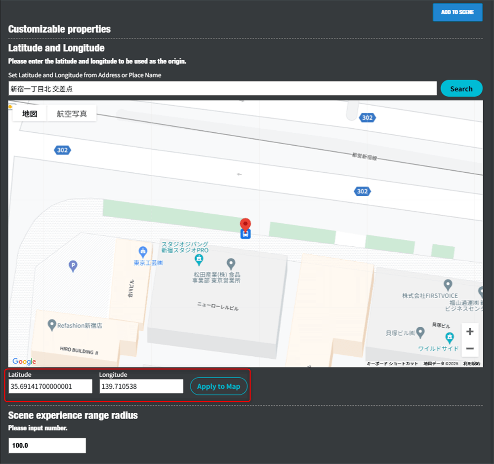
The post City Anchor usage manual first appeared on STYLY.
]]>The post Hyper Music Venue Urban AR Production Guide first appeared on STYLY.
]]>What’s “Hyper Music Venue”?

“Hyper Music Venue” is a project where XR creators and artists create new music venues—spaces for musical experiences. It aims to transform cities into live stages, going beyond the limitations of specific places and times like live houses and domes. How creators utilize the buildings, streets, streetlights, railways, and even the sky is entirely up to them.
The first featured artist is “でんぱ組.inc.” Using their artist assets, creators are invited to take on the challenge of creating AR experiences that resonate with urban spaces. Additionally, a total of 3 million yen in support funds is provided for creators, supporting their activities even after production.
Transcend conventions and dimensions, and create music experiences and worlds no one has ever seen before with your own hands. We look forward to the participation of many XR creators.
Hyper Music Venue application site:https://hypermusicvenue.com
Hyper Music Venue Unity Package Download
Hyper Music Venue Unity Package Download Link
You can download the Unity package required for playing volumetric data from the above link.
Download List
- HoloStreamSimplePlay Custom Action (distributed to those who agree to the terms)
- HoloSuite Unity Player (distributed to those who agree to the terms)
- Hyper Music Venue.unitypackage (distributed to those who agree to the terms)
Preparing the Production Environment
- Unity 2022.3.24f1
- PlayMaker 1.9.8
- HoloStreamSimplePlay Custom Action (distributed to those who agree to the terms)
- Hyper Music Venue.unitypackage (distributed to those who agree to the terms)
- HoloSuite Unity Player (distributed to those who agree to the terms)
Please prepare Unity 2022.3.24f1 and PlayMaker.
Import the packages into your Unity project in the following order.
① Download Unity 2022.3.24f1
Type unityhub://2022.3.24f1/334eb2a0b267 into the search form of your web browser and download Unity 2022.3.24f1 from Open Unity Hub. Alternatively, you can download Unity 2022.3.24f1 from the Unity Download Archive.
② Download/Import PlayMaker
Purchase PlayMaker from the PlayMaker page on the Unity Asset Store.
Import PlayMaker into Unity.
Refer to the following article for instructions on how to use PlayMaker.
https://styly.cc/ja/tips/unity-playmaker-learn-the-basics/#
③ Download/Import STYLY Plugin for Unity
Download the STYLY Plugin for Unity DOWNLOAD and import it into Unity.
④ Import HoloStreamSimplePlay Custom Action
Import the STYLYCustomActionHoloStream.unitypackage.
Please review the asset usage terms, and only those who agree may download the Unity package. The Unity package download link is displayed only to those who agree to the asset usage terms.
⑤ Download and Import Unity Package for Hyper Music Venue
Import HyperMusicVenue.unitypackage into Unity.
Please review the asset usage terms, and only those who agree may download the Unity package. The Unity package download link is displayed only to those who agree to the asset usage terms.
⑥ Download and Import HoloSuite Unity Player
Import the HoloSuite Unity Plugin into Unity.
Please review the asset usage terms, and only those who agree may download the HoloSuite Unity Player. The Unity package download link is displayed only to those who agree to the asset usage terms.
In the Unity Editor, open the Window menu > Package Manager.

In the Package Manager window, click the “+” button in the upper left and select “add package from tarball…”

Select the HoloSuite Unity Plugin 4.0.x fix2.tgz file.

Please wait for the installation to complete.

Select STYLY menu > HoloStreamPlayer Setting > Enable HoloStreamPlayer preview to activate the volumetric data preview feature in Unity Editor.

How to Use the Sample Project
Click on Project window > Scene > Hyper Music Venue to open the scene.

The sample scene contains a 3D model of Shibuya Scramble Crossing, with game objects that incorporate logic for randomly appearing members of でんぱ組.inc with each playback.
Under “Dempa Random ALL Scale 20 (Upload),” the HoloStream object has logic built with PlayMaker to play volumetric data. The volumetric data (including music data) is streamed and works only when playing the Unity scene.

Play the scene (Note: there will be sound). Confirm that the volumetric data of でんぱ組.inc is displayed.

*Not working on macOS Big Sur version 11.6.1, please update to macOS Monterey version 12.7.2.
Important Notes
- Do not change the scale from 20.
- Do not modify the random playback mechanism.
- Do not place members outside the Shibuya Scramble Crossing (fine adjustments are allowed).
- The resolution of the volumetric data may vary depending on the network environment.
- The distribution of the volumetric data will end on February 28, 2025, at 12:00 PM.

Upload the Created Prefab to STYLY
Create a Prefab by consolidating everything into a single game object. Do not include the data of the Shibuya Scramble Crossing.

Right-click on the Prefab you want to upload to STYLY > STYLY > Upload prefab or Scene to STYLY.

Troubleshooting during STYLY Upload
When “Asset Upload failed AzcCopy enabled but exec file not found” is displayed

Click on Main Menu > STYLY > Asset Uploader Settings.

Check the box for Enable AzCopy.

Create a Scene in STYLY Studio
Access STYLY Studio and click the New Scene button.

Enter the scene title. Since full-width (Japanese) input is not allowed, please use half-width alphanumeric characters.

Select Tokyo Shibuya Station and click the Create Scene button.

Select the Asset menu.

Select My uploads.

Select Unity.

Select the Prefab uploaded from Unity.

Objects containing volumetric data will be displayed with a scale image like this. Position this scale at the center of the Shibuya Scramble Crossing and adjust it by pointing the arrow toward Your Position.

Important Notes
- The displayed scale (2.0m, 2.4m, etc.) differs from the actual scale.
- Volumetric data will not play in WebGL environments (STYLY Studio and Web Player).
Distribute AR City Live Scenes with STYLY
Click the PUBLISH icon.

Click the Go to publish button.

Add the tag HMV2024 (you can add tags by pressing the enter key) and PUBLISH it. Make sure to include the HMV2024 tag. The tag can be edited later.

Edit the Thumbnail and Tags of the STYLY Scene
Click the pen icon.

You can edit the title, description, thumbnail, and tags. Upload the thumbnail in JPEG format with a size of 1920×1080px and less than 2MB. The thumbnail will be submitted through the application form.

STYLY Mobile App System Requirements
The recommended system requirements are as follows:
Each AR-compatible device = STYLY Mobile compatible device.
iPhone, iPad: Please refer to the following for Apple’s official list of AR-compatible devices:
https://www.apple.com/jp/augmented-reality/
Android devices: Please refer to the following for Google’s official list of AR-compatible devices:
https://developers.google.com/ar/discover/supported-devices#google_play_devices
How to Download the STYLY Mobile App
AppStore

GooglePlay

How to Experience AR Live (On-site Verification)
Move to the Shibuya Scramble Crossing. The AR live using the Tokyo Shibuya Station city template can only be experienced when you are physically at the Shibuya Scramble Crossing.
Launch the STYLY Mobile app near the Shibuya Scramble Crossing, tap My Page, and then tap the AR live you created.

Tap the View button and point your camera towards the Shibuya Scramble Crossing.

A giant でんぱ組.inc will appear at the Shibuya Scramble Crossing.
Since the volumetric data is streamed, playback time may vary depending on the signal strength of various carriers.

Share Your AR Live Experience Video on Social Media
Post the following information on social media platforms (TikTok, Youtube Shorts, X (formerly Twitter)):
- URL of the AR city live,
- Hashtags:
- #でんぱ組.inc
- #STYLY
- AR live experience video
You can copy the URL of the AR city live from the share menu.

How to Post AR Live Experience Videos on TikTok (Sound Settings)
Set the sound to Future Diver (10th Anniversary Ver.) 00:24.

Mute the original audio.

How to Post AR Live Experience Videos on Youtube Shorts (Sound Settings)
Set the sound to Future Diver (10th Anniversary Ver.).

Set the additional audio to 0%.

Set the sound start time to 1:08-.

Contact Us
For technical questions related to Unity and STYLY, please use the STYLY Forum.
For other inquiries regarding terms, please contact [email protected].
The post Hyper Music Venue Urban AR Production Guide first appeared on STYLY.
]]>The post Introduction to Unity Visual Scripting Part 10: Cooperation with STYLY For Vision Pro first appeared on STYLY.
]]>In this article, we’ll explain how to integrate Visual Scripting with STYLY for Vision Pro.
Download the sample scene that summarizes the features available in STYLY for Vision Pro.
Use Unity version 2022.3.27f.
This tutorial will show you how to grab an object and apply some effect to it.
Grabbing Objects with Visual Scripting
Open the downloaded project in Unity Hub.
Click the Add button.

Open the downloaded project in Unity Hub
Select the downloaded folder and click Open to open the project.

Open the project
Click the + button at the bottom of the Project tab, select Scene, and create a new scene.

Create a new scene
For this tutorial, name the scene [GrabScene].

GrabScene
Next, create the object to be grabbed. Click the + button in the Hierarchy, select 3D Object → Cube, and create a cube.

Select 3D Object → Cube to create a cube
Name it [GrabCube] and add the XR Grab Interactable component.

Add the XR Grab Interactable component
XR Grab Interactable is a component that allows objects to be grabbed in the XR space.
This C# script is integrated with STYLY for Vision Pro, so you can use it directly.
Changing the Color of Grabbed Objects with Visual Scripting
XR Grab Interactable has many functions.
If you want to learn more about its features, refer to the Unity manual.
Open the Interactable Event section in the XR Grab Interactable component.

Open the Interactable Event in XR Grab Interactable
Click the + button for both Select and Select Exited, then drag and drop as shown below.

Drag and drop to add
Click No Function, then select Script Machine → TriggerUnityEvent.

Script Machine → TriggerUnityEvent
In Select, enter [StartGrab] as shown below.

StartGrab
For Select Exited, enter [ExitGrab].
Select triggers actions when the object is grabbed.
Select Exited triggers actions when the object is released.
Attach a Script Machine to the [GrabCube] object.
Change the Source to Embed.

Change Source to Embed
Click Edit Graph to display the Script Graph.
Add the following nodes to the Graph Editor:
- UnityEvent
- Renderer Get Material
- Color Literal
- Set Color
Note: Images are provided for nodes that might be unclear.

Renderer Get Material

Set Color
Connect the nodes as shown below.
In the UnityEvent node, enter [StartGrab] as set in the XR Grab Interactable’s Select event. Set the Color to the color you want when the object is grabbed; in this case, it’s set to red.

StartGrab
Select all the connected nodes, and duplicate them by pressing Ctrl+D (or Cmd+D on Mac).
Similarly, enter [ExitGrab] in the UnityEvent node and set the Color to the color you want when the object is released. In this case, it’s set to white.

ExitGrab
Uploading to STYLY for Vision Pro
In Unity, the Transform units are in meters. The current [GrabCube] might be too large, so resize it to a 30 cm cube.

Resizing the cube to 30 cm per side
The [GrabCube] has a RigidBody attached, so gravity will cause it to fall. To prevent this, create a base for it to sit on.
Create a new Cube in the scene and position it underneath the [GrabCube]. You don’t need to change its size.

Placing the base
When uploading multiple objects, group them together and create a Prefab.
Create an empty GameObject, name it [GrabPrefab], and move both the [GrabCube] and the base under it.

Prefab creation
Drag and drop the [GrabPrefab] into the Project window to create a Prefab (you’ll see the icon turn blue).

Drag and drop GrabPrefab into the Project window
Right-click on the Prefab [GrabPrefab] and select STYLY → Build prefab.

STYLY → Build prefab
Your browser will open automatically.
After creating an account and logging in, you’ll see a screen like this. Click on [+ New content].

+ New content
Set a title—[GrabColor] is used in this example.
Next, drag and drop the generated folder from the [_Output] folder within your project into the Select file section, then click Upload to finish.
All other settings remain at their default values.

Upload
This time, we introduced how to integrate Visual Scripting with STYLY For Vision Pro.
The post Introduction to Unity Visual Scripting Part 10: Cooperation with STYLY For Vision Pro first appeared on STYLY.
]]>The post Introduction to Unity Visual Scripting Part 9: Animation and Audio first appeared on STYLY.
]]>In this article, we will explain how to create and play animations using Visual Scripting, as well as how to play audio.
Creating Animations in Unity
Animation is a feature built into Unity that allows you to create animations by setting keyframes.
To play the animation created using Visual Scripting, let’s first create the object to be animated.
Click the + button in the Hierarchy, select 3D Object → Cube to create a Cube.

3D Object → Cube
Name it [AnimationCube].

AnimationCube
From the top menu bar, select Window → Animation → Animation to open the Animation window.

Animation Window
With [AnimationCube] selected, click the Create button in the Animation window.

Create in the Animation Window
Set the Position of AnimationCube to (10, 0, 0).

Set Position to (10, 0, 0)
Click Add Property, then click the + next to Transform → Position.

Transform → Position
This time, we will make the object move back and forth.
Move the timeline to 0:30 and set Position.x to -10.

Set Position.x to -10
Click the play button in the Animation window to play the animation.

Play Button in Animation Window
The animation is now playing.

Playing the Animation
Playing Animations with Visual Scripting
Click the + button in the Hierarchy and select Create Empty to create an empty GameObject.
Name it [UXManager].
“`html

UXManager
Attach a Script Machine to [UXManager].
Create a folder named Macros, and inside it, create a Graph named [UXController].

UXController
Double-click AnimationCube in the Animations folder to open the Animator window.

Animator Window
Right-click on CubeAnimation and select Delete.

Delete
In the empty space of the Animator window, right-click and select Create State → Empty.

Create State → Empty
Drag and drop CubeAnimation from the Animations folder into the Animator window.

Drag and drop CubeAnimation into the Animator window
Right-click on the New State and select Make Transition, then connect the arrow to CubeAnimation.

Connect the arrow to CubeAnimation
Click the + button in the Parameters section of the Animator window, select Bool, and name it [Play].

Play
Select the arrow connecting New State and CubeAnimation in the Animator window, and click the + button in the Conditions section of the Inspector.
By doing this, the next animation will play when [Play] becomes True.

Click the + button in the Conditions section of the Inspector
Set the animation to play when the spacebar is pressed.
Create a GameObject variable in Variables named [Cube] and set the Value to [AnimationCube].
Add [Cube] to the Graph Editor.
![Add [Cube] to the Graph Editor](proxy.php?url=https://styly.cc/wp-content/uploads/2024/08/19-3.png)
Add [Cube] to the Graph Editor
Add the following nodes to the Graph Editor.
*Only the nodes that are difficult to understand are shown in the images.
- Get Key Down (Key)
- If
- SetBool (Name, Value)

SetBool (Name, Value)
Connect the nodes as shown below.
Set the Bool Name to [Play], which was set in the Animator.
Since we set the animation to play when [Play] is True, check the Value box.

Connect the nodes
Press play. The animation will play when the spacebar is pressed.

Playing the Animation
Playing Audio with Visual Scripting
This time, we will use free audio.
You can download the audio from this download page.
You can also use any audio you like.
“`html
Drag and drop the downloaded audio file directly into the Assets folder.

Drag and drop the downloaded audio file into the Assets folder
Click the + button in the Hierarchy, then select 3DObject → Cube to create a Cube.
Name the Cube [SpeakerCube].

SpeakerCube
Click AddComponent on SpeakerCube and add the [Audio Source] component.

Audio Source
Add a GameObject variable named [Speaker] to UXManager’s Variables.
Set the Value to [SpeakerCube]. Add [Speaker] to the Graph Editor.
![Add a GameObject variable named [Speaker]](proxy.php?url=https://styly.cc/wp-content/uploads/2024/08/26-1.png)
Add a GameObject variable named [Speaker]
Add the following nodes to the Graph Editor.
*Only the nodes that are difficult to understand are shown in the images.
- On Update
- Get Key Down (Key)
- If
- Set Clip
- Play

Set Clip

Play
Drag and drop the downloaded audio file into the Graph Editor.
A window like the one below will appear; select the top option.

Drag and drop the downloaded audio file into the Graph Editor
Connect the nodes as shown below.
Set the space key for Get Key Down.
Set Clip Node: You can set the audio file in the Audio Source’s Audio Clip.
Connect the object with the Audio Source attached to the middle-left port.
Connect the audio file to the bottom-left port of the Audio Source’s Audio Clip.
“`html
Play Node: This node plays the audio file set in the Audio Clip of the Audio Source.
Connect the object with the Audio Source attached to the bottom-left port.

Connect the nodes
Press the play button to run the scene. The AnimationCube begins to move along with the music.

Run the scene
This time, we introduced how to animate and play audio using Visual Scripting.
Next time, we’ll cover integration with STYLY for VisionPro.
The post Introduction to Unity Visual Scripting Part 9: Animation and Audio first appeared on STYLY.
]]>The post Introduction to Unity Visual Scripting Part 8: Creating a target game using Raycast and List (Part 2) first appeared on STYLY.
]]>
This article is part of a two-part series explaining how to create a shooting game using Raycast and List.
In this article (the second part), you will learn:
- Raycast
- Destroy
- Removing elements from a List
- How to use Tags
Using Raycast to Retrieve Object Information
A Ray is a beam of light emitted in a specified direction, and it can be used to obtain information about the objects it hits.
Add a GameObject type variable named [Camera] to the Variables.
Assign the MainCamera in the scene to the Value.
Add [Camera] to the Graph Editor.
![Add [Camera] to the Graph Editor](proxy.php?url=https://styly.cc/wp-content/uploads/2024/08/1-3.png)
Add [Camera] to the Graph Editor
Add the following to the Graph Editor:
- On Update
- Get Key Down
- If
- Get Mouse Position
- Screen Point To Ray
- RayCast
※ Only unclear node images are provided.

Screen Point To Ray

RayCast
Enter Mouse 0 (left-click) for the Key in Get Key Down.
The GIF shows what happens when you enter Mouse 0 for the Key in Get Key Down, which isn’t visible without scrolling.

Enter Mouse 0 in the Key field of Get Key Down
Connect the nodes as shown below.
By connecting the Camera component and Mouse Position to the left port of Screen Point To Ray, it creates Ray information from the camera. Connecting this to Raycast allows you to shoot a Ray.

Connect nodes
Let’s confirm whether the Ray is being cast successfully.
Add the following nodes to the Graph Editor:
- Debug Log (Message)
- Get Collider
- Get Game Object

Get Collider

Get Game Object
Connect the nodes as shown below.
The Collider of the object hit by the Ray is obtained, and from there, the object’s information is retrieved to display the name of the target in the Console.

Connect nodes
Run the scene. You can display the name of the target you clicked.

Run the scene
Delete the Retrieved Object
As part of the game elements, let’s first create a floor.
Click the + button in the Hierarchy, then click 3D Object → Plane to create a Plane.
Set the Plane’s Transform as shown below.

Set the Plane’s Transform
Next, register a new Tag to distinguish between the floor and targets.
Tags allow you to categorize objects, enabling you to change the processing based on the object’s Tag.
Click on the Tag of the [Target] prefab in the Project and then click Add Tag.

Click Add Tag
Click the + button, enter [Target] in the New Tag Name field, and then click Save.
This registers a new Tag.
Now, the [Target] prefab has the [Target] Tag, allowing you to perform operations based on this Tag.

Register a new Tag
Add the following nodes to the Graph Editor:
- If ×2
- String Literal
- Get Tag
- Equal
- Destroy
- Aot List Remove
※ Only unclear node images are provided.
Add [TargetList] from the Variables.

Get Tag

Destroy

Aot List Remove
Connect the nodes as shown below. Enter “Target” in the String.
Here is an explanation of the nodes:
- The middle-right port of Raycast checks if the Ray hits an object. If it hits, it returns True; if it doesn’t, it returns False. In this case, if the Ray hits, the process moves to the next step.
- The Tag of the GameObject is retrieved, and if it matches [Target], it returns True, proceeding to the next step.
- The middle-left port of Remove connects to the list containing the object to be removed.
The bottom port connects to the object to be removed from the list.
If you don’t remove the object from the list before deleting it, an error may occur. Therefore, you remove the object from the list first, and then delete the object using the Destroy node by connecting the object to the bottom-left port.

Connect nodes
Run the scene.

Run the scene
And with that, the project is complete. Below is an example that includes a scoring feature, which was created after reviewing Unity Visual Scripting tutorials in Parts 3 and 4.
If you have extra time, give it a try!

With scoring feature
![Introduction to Unity Visual Scripting Part 3: How to calculate time and score [Part 1 of the continuous hit game]](https://styly.cc/wp-content/uploads/2024/08/23-1-160x160.png)
![Introduction to Unity Visual Scripting Part 4: Switching screens and displaying scores [Part 2 of the continuous hit game]](https://styly.cc/wp-content/uploads/2024/08/11-1-160x160.png)
If you get stuck, you can check the completed sample here:
https://github.com/Manufuki/HitTargetSample.git
In the next installment, Part 9, we’ll cover how to play sounds and animations using Visual Scripting.
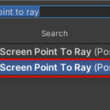
The post Introduction to Unity Visual Scripting Part 8: Creating a target game using Raycast and List (Part 2) first appeared on STYLY.
]]>The post Introduction to Unity Visual Scripting Part 7: Creating a target game using Raycast and List (Part 1) first appeared on STYLY.
]]>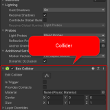
This article is divided into two parts and explains how to create a target shooting game using Raycast and List.
What you will learn in this part (Part 1):
- Adding elements to a List
- Random
- For loops
- Instantiate
Final Image

Final Image
Create Random Coordinates with the Random Function
The Random function outputs a random number within a specified range.
Click the + button in the Hierarchy and create an empty GameObject.

Create a GameObject
Name it [AimLabManager].
![[AimLabManager]](proxy.php?url=https://styly.cc/wp-content/uploads/2024/08/3-5.png)
[AimLabManager]
Attach a Script Machine to [AimLabManager], create a new graph in a folder called Macros, and save it there.
Name the graph [AimLabGraph].
![[AimLabGraph]](proxy.php?url=https://styly.cc/wp-content/uploads/2024/08/4-4.png)
[AimLabGraph]
Since we want to generate targets every few seconds, we need to set a timer.
Add a variable to measure time. Add a Float variable [Time] to the Variables in [AimLabManager], and add [Time] to the Graph Editor.
![Add a Float variable [Time] to [AimLabManager]](proxy.php?url=https://styly.cc/wp-content/uploads/2024/08/5-5.png)
Add a Float variable [Time] to [AimLabManager]
Add the following nodes to the Graph Editor.
- Get Delta Time
- Add
- If
- Greater
- Set Object Variable ×2
- Float Literal
※ Only unclear node images are provided.

Get Delta Time

Add
Connect the nodes as shown below.
This time, we will generate a target every 0.5 seconds, so input 0.5 into Greater.
If the time exceeds 0.5 seconds, the [Time] will be reset to zero. Therefore, two Set Object Variable nodes are prepared.

Prepare two Set Object Variable nodes
Next, we will create random coordinates. Add Random Range and Vector3 Create(X, Y, Z) to the Graph Editor.
Select the Random Range with Result (Float Output).
If you choose the Int type, the random numbers will be integers.
This time, we will add randomness with a Float variable.
Also, since we want to add randomness to the X and Y axes, create two Random Range nodes.

Random Range

Vector3 Create(X, Y, Z)
Connect the nodes as shown below.
The upper variable in Random Range is the minimum value, and the lower variable is the maximum value, which will generate a random number within that range.
This time, set the X-axis to -4 to 4 and the Y-axis to 0 to 3.

Connect nodes
Use Instantiate to Create Objects and Add Them to the List
We can use Instantiate to create objects, so we’ll use it to create the targets.
First, create a Prefab for the target. Click the + button in the Hierarchy, then click 3D Object → Sphere to create a Sphere.
Name it [Target].

Create a Sphere
Drag and drop Target into the Asset folder in the Project window to turn it into a Prefab.

Drag and drop to create Prefab
After converting it to a Prefab, delete the Target from the Hierarchy.
Drag and drop the Prefabbed Target into the Graph Editor, and when the following window appears, press Enter to add it.

Drag and drop the Prefabbed Target into the Graph Editor
Add Instantiate and Get Identity to the Graph Editor.

Instantiate, Get Identity

Instantiate, Get Identity
Connect the nodes as shown below. Here is an explanation of each port on the Instantiate node:
| Original Port | Connect the Prefab of the object to be instantiated. |
| Position Port (Vector3 variable) | Connect the position of the object to be instantiated. |
| Rotation Port (Quaternion variable) | Connect the rotation of the object to be instantiated. |
Get Identity contains a Quaternion value of (0,0,0,1).

Connect nodes
Run the program. A [Target] is now generated at random coordinates.
![Generate [Target] at random coordinates](proxy.php?url=https://styly.cc/wp-content/uploads/2024/08/18-1.gif)
Generate [Target] at random coordinates
Use a For Loop to Assign Numbers to the Objects in a List
Add an Aot List type List variable. Name it [TargetList] and add it to the Graph Editor.

Add an Aot List type List variable
Add the following nodes to the Graph Editor:
- Add Item
- Count Item
- For Loop
- Get List Item
- Integer To String
- Set Name
※ Only unclear node images are provided.

Integer To String

Get List Item

Set Name
Connect the nodes as shown below.
The instantiated object is output from the lower right port of Instantiate, so use Add Item to add it to the list.
The middle left port of Add Item connects to the list to which you want to add, and the lower port connects to the object to be added to the list.
After that, rename the Targets in the list.
The For Loop repeats the process connected to the Body for a specified number of times.
The First port has the initial value input.
The value in the Step port is added to the First value with each iteration, and when it equals the Last value, the For Loop ends, and the process exits through the Exit port.
Here’s what happens after the Body:
The Index outputs the current loop count as an Int.
To String is used to convert the Index to a String.
The list is numbered starting from 0 based on the order in which items are stored.
Get Item retrieves the information stored in the list at the number connected to the Index.
Finally, Set Name is used to rename the objects.
The object to be renamed is connected to the second port from the top, and the new name is connected to the port below it.

Connect nodes
Run the program. The generated objects can now be numbered sequentially from 0.

Objects numbered sequentially from 0
Limit the Number of Targets Generated
Add the [Target List] variable to the Graph Editor.
Add the following nodes to the Graph Editor:
- Count Items
- Greater
- If
※ Only unclear node images are provided.

If
Add these nodes after On Update.
This time, we will generate up to four objects.
Enter 3 into Greater (the count starts at 0, so 0 through 3 counts as four items).
When the elements in [Target List] exceed 4, Greater will return True, preventing the process after If from executing.

Connect nodes
Run the scene. You can now limit the number of targets generated to four.

Limit the number of targets generated to four
Here is an overview of all the Visual Scripting nodes used this time.

Overview of the nodes
The next article will introduce a mechanism where targets disappear when clicked.
The post Introduction to Unity Visual Scripting Part 7: Creating a target game using Raycast and List (Part 1) first appeared on STYLY.
]]>The post Introduction to Unity Visual Scripting Part 6: How to add collision detection with Collision first appeared on STYLY.
]]>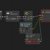
This time, we will explain how to implement collision detection using Collision.
Collision-Based Hit Detection
Add an empty GameObject to the Hierarchy and name it [HitManager].
![[HitManager]](proxy.php?url=https://styly.cc/wp-content/uploads/2024/08/1-2.png)
[HitManager]
Attach a Script Machine to [HitManager], create a new graph in a folder called Macros, and save it there.
Name the graph [HitGraph].
![Attach Script Machine to [HitManager], save it in the Macros folder, and rename the graph to [HitGraph].](proxy.php?url=https://styly.cc/wp-content/uploads/2024/08/2-3.png)
Attach Script Machine to [HitManager], save it in the Macros folder, and rename the graph to [HitGraph].
Click the + button in the Hierarchy and create a Cube from 3D Object. Name it [TopObj].
![[TopObj]](proxy.php?url=https://styly.cc/wp-content/uploads/2024/08/3-4.png)
[TopObj]
Set the Position of [TopObj] to (0, 5, 0), and attach a Rigidbody from AddComponent.
Make sure to uncheck the Is Trigger option in the Box Collider.
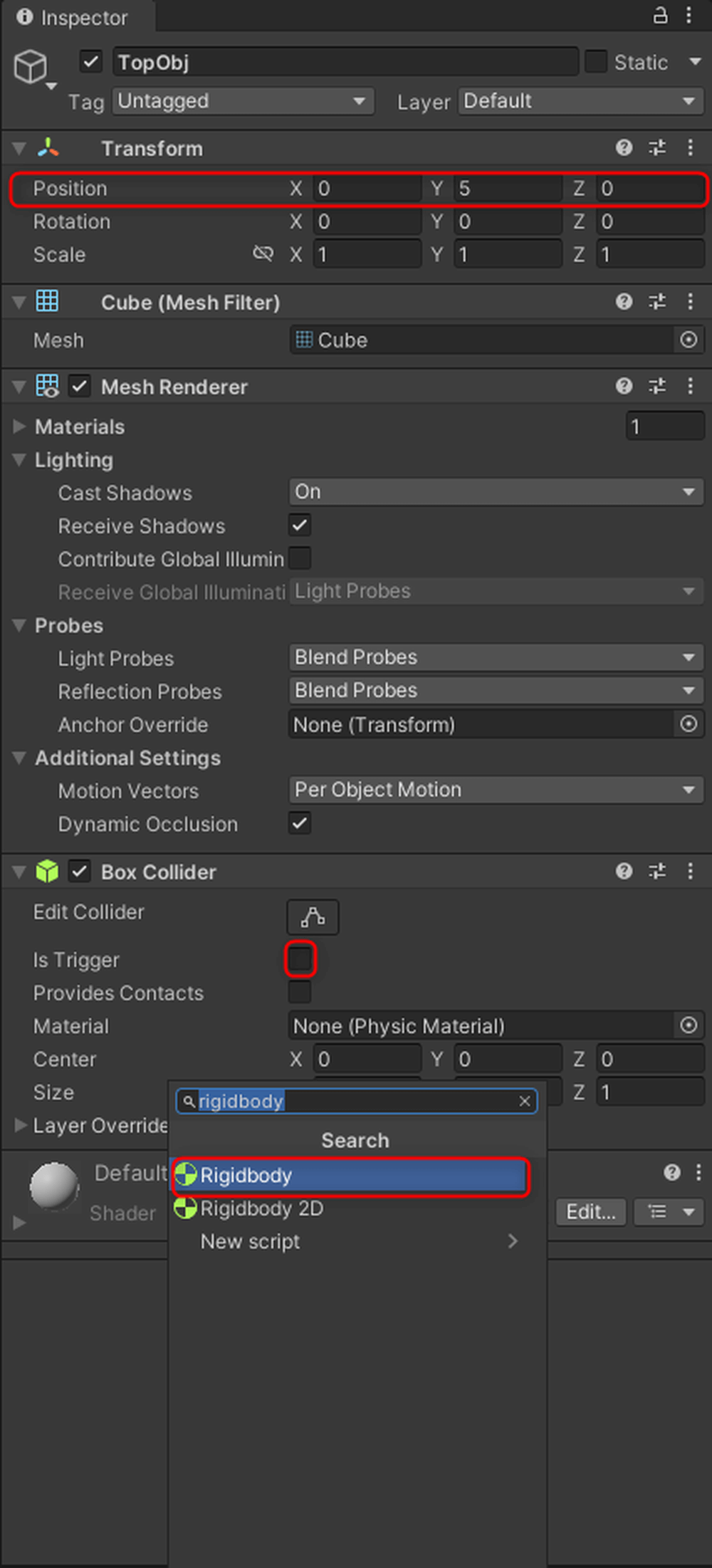
Attach Rigidbody and uncheck Is Trigger in Box Collider.
Next, add another Cube to the Hierarchy and name it [UnderObj].
Set the Position of [UnderObj] to (0, 0, 0).
![[UnderObj], (0, 0, 0)](proxy.php?url=https://styly.cc/wp-content/uploads/2024/08/5-4.png)
[UnderObj], (0, 0, 0)
Preparation is complete.
Add a GameObject type variable [HitObj] to the HitGraph’s Variables in [HitManager], and set its Value to TopObj.
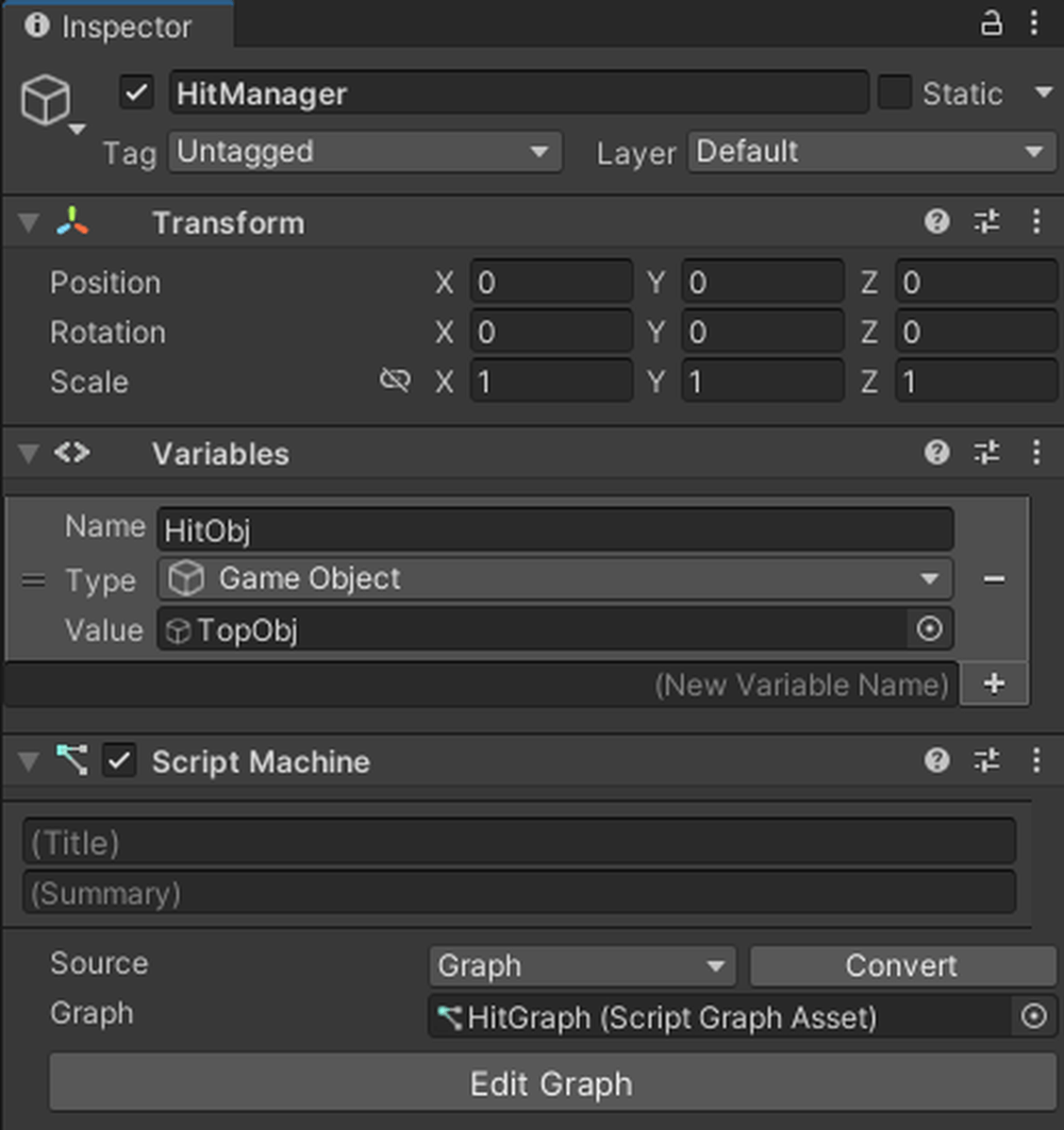
Set Value to TopObj
Add On Collision Enter, Debug.Log, and String Literal to the Graph Editor, and add [HitObj] from Variables.
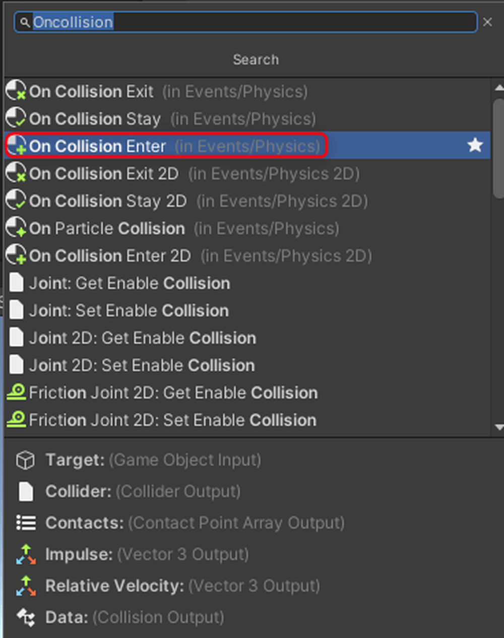
Add On Collision Enter, Debug.Log, String Literal
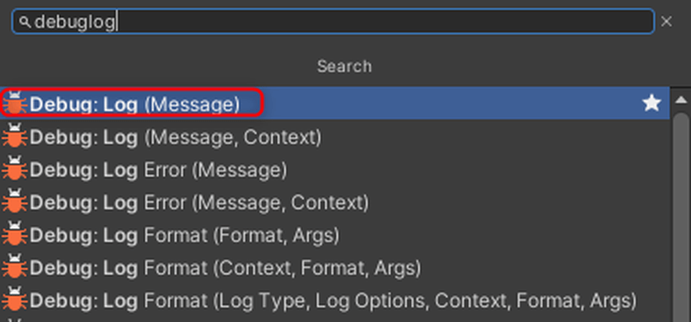
Add On Collision Enter, Debug.Log, String Literal
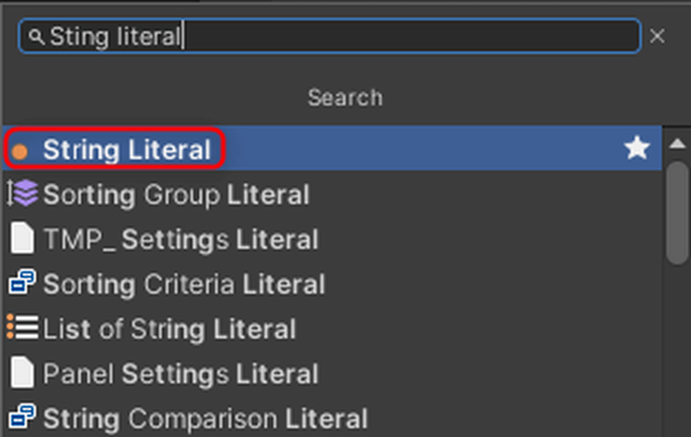
Add On Collision Enter, Debug.Log, String Literal
This Collider is what will be used for collision detection.

Collider
On Collision EnterThis node is executed when objects with Colliders collide.On Collision StayThis node is executed continuously while objects with Colliders are in contact.On Collision ExitThis node is executed when objects with Colliders separate.
The left port connects to the object that is involved in the collision.
The right port contains information about the object that the Collider has collided with.
The Contacts port stores the collision points, normals, and the two colliders involved in the collision.
The Impulse port stores the impact of the collision.
The Relative Velocity port stores the relative speed of the other object at the time of collision.
The Data port contains information about the other object.
Connect the nodes as shown below. In this case, we will have On Collision Enter execute when something collides with HitObj.

Connect nodes
Run the program.
![Displaying the collided object's information [UnderObj] in the Console](proxy.php?url=https://styly.cc/wp-content/uploads/2024/08/11-1.gif)
Displaying the collided object’s information [UnderObj] in the Console
When objects collide, the information of the collided object [UnderObj] is displayed in the Console.
Hit Detection Using Triggers
Check the Is Trigger box on the Box Collider of [TopObj].

Check Is Trigger
By checking Is Trigger, the objects will no longer collide with each other and will pass through each other.
Add On Trigger Enter to the Graph Editor.

Add On Trigger Enter
Disconnect On Collision Enter and connect the nodes as shown below.

Connect nodes
Since Trigger does not involve actual contact, there is no information such as collision points or impacts.
| On Trigger Enter | This node is executed when objects with Colliders touch each other. |
| On Trigger Stay | This node is executed continuously while objects with Colliders are in contact. |
| On Trigger Exit | This node is executed when objects with Colliders separate. |
Run the program.
![Displaying the collided object's information [UnderObj] in the Console](proxy.php?url=https://styly.cc/wp-content/uploads/2024/08/15.gif)
Displaying the collided object’s information [UnderObj] in the Console
When the objects touch each other, the information of the touched object [UnderObj] is displayed in the Console.
This time, we covered how to create collision detection.
In the next session, we will introduce Raycast and List.
You can check the next article from the link below.
The post Introduction to Unity Visual Scripting Part 6: How to add collision detection with Collision first appeared on STYLY.
]]>The post Introduction to Unity Visual Scripting Part 5: Basic operations on objects using AddForce and TransForm first appeared on STYLY.
]]>This time, we will explain the basic operations of objects using AddForce and Transform.
Moving with AddForce
Add an empty GameObject to the Hierarchy and name it [ObjectController].
![Rename GameObject to [ObjectController]](proxy.php?url=https://styly.cc/wp-content/uploads/2024/08/1-1.png)
Rename GameObject to [ObjectController]
Attach a Script Machine to [ObjectController].
Click New to create a graph.
![Attach Script Machine to [ObjectController]](proxy.php?url=https://styly.cc/wp-content/uploads/2024/08/2-2.png)
Attach Script Machine to [ObjectController]
Click New on the Script Machine to create a graph.
Create a folder named Macros, and save it as [ObjectManager] within that folder.
![Create a folder and save it as [ObjectManager]](proxy.php?url=https://styly.cc/wp-content/uploads/2024/08/3-3.png)
Create a folder and save it as [ObjectManager]
Add a Cube to the Hierarchy, set its Position to (0, 0.5, 0), and add a [Rigidbody] from AddComponent.
This time, we will move this object.
![Set Cube Position to (0, 0.5, 0) and add [Rigidbody] from AddComponent](proxy.php?url=https://styly.cc/wp-content/uploads/2024/08/4-2.png)
Set Cube Position to (0, 0.5, 0) and add [Rigidbody] from AddComponent
Rigidbody is a feature in Unity that handles physics calculations.
It allows you to add gravity or apply forces to an object.

Rigidbody
Next, add a Plane to the Hierarchy to place this object on.

Add Plane
Set its Position to (0, 0, 0).
Add a GameObject type variable to the ObjectController’s Variables, name it [Cube], and set its Value to the Cube.

Add a GameObject type variable to the ObjectController’s Variables.
Add nodes to respond when the space key is pressed, and connect them as shown below.

Connect nodes
Add an Add Force node to the Graph Editor.
Enter the direction you want to apply force in the Force value.

Add Force
AddForce is a node that applies force to an object.
This time, we want to make the object jump, so we entered (0,300,0). Feel free to try other values.
The second node from the top of AddForce connects to the object you want to move.
Add [Cube] from Variables to the Graph Editor, and connect the nodes as shown below.

Connect nodes
Run the program.

Jump with the space key
Press the space key to jump.
Moving Objects with Transform
Movement
Add Get Position, Set Position, Vector3Literal, and Add to the Graph Editor.

Add Get Position, Set Position, Vector3Literal, and Add

Add Vector3Literal
Disconnect AddForce and remove the Rigidbody from the Cube.
To remove a component that has been added, click the three dots on the right and select Remove Component.

Disconnect AddForce and remove Rigidbody
Add another Cube from Variables to the Graph Editor. In Vector3Literal, enter the distance to move when the space key is pressed.
This time, enter (0,1,0).
Get Position retrieves the coordinates of the object connected to the node.
Set Position assigns the coordinates connected to the bottom port to the position of the node connected to the middle port.
Reconnect the nodes as shown below.

Connect nodes
Let’s run it.

Moved up
Scaling
Add Get Local Scale and Set Local Scale to the Graph Editor.

Add Get Local Scale and Set Local Scale
Disconnect the Get Position and Set Position connections.
Change the value of Vector3Literal to (1,1,1).
Get Local Scale retrieves the scale of the object connected to the node.
Set Local Scale assigns the scale connected to the bottom port to the scale of the node connected to the middle port.
Connect the nodes as shown below.

Connect nodes
Run the program. The object will grow by 1 meter each time you press the space key.

Grows larger with each press of the space key
Rotation
Add Rotate to the Graph Editor.

Add Rotate to the Graph Editor
Rotation is calculated differently from Position and Scale, so a separate function called Rotate is provided.
Disconnect the nodes used for scaling, and reconnect them as shown below.
This time, we will rotate the object by 30 degrees each time, so enter (30,0,0) for the Vector3 value.
For Rotate, connect the current angle to the second port from the top, and the amount to rotate to the third port from the top.

Connect nodes
Run the program. Each press of the space key rotates the object by 30 degrees.

Rotates 30 degrees with each press of the space key
Rotating to a Specific Angle
Add Euler (Euler) and Set Rotation to the Graph Editor.

Add Euler (Euler) and Set Rotation

Add Set Rotation
Disconnect the nodes used for rotation and reconnect them as shown below. Set the value of Euler to (0,30,0).
For Set Rotation, connect the object to be modified to the middle port and connect the Quaternion type variable to the bottom port.

Connect nodes
Run the program. When you press the space key, the Cube rotates 30 degrees on the Y-axis.

Rotates 30 degrees on the Y-axis when the space key is pressed
This time, we learned how to move objects.
In the sixth session, we will introduce collision detection.
You can check the next article from the link below.
The post Introduction to Unity Visual Scripting Part 5: Basic operations on objects using AddForce and TransForm first appeared on STYLY.
]]>The post [Unity/PlayMaker] How to use Post Processing Stack V1 first appeared on STYLY.
]]>This time, we will explain how to use a post-processing method that can also be used with the STYLY mobile app. This method can be used in both AR and VR scenes.
In this article, we will use Post Processing Stack V1 and PlayMaker (paid).
What is post-processing?
Post-effects refers to the application of effects (filters) to “the result of rendering the information (3D model, lights, etc.) captured by the camera on the display.
Think of the camera application “SNOW” or the image editing software “Photoshop”.
In Unity, the Post Processing Stack provided by Unity can be used by downloading and importing the Post Processing Stack from the Package Manager.
This is a useful feature because it allows you to improve the quality of a scene in a few simple steps.
Introduction
We will use Unity2022.3.27f1.
First, install the STYLY Plugin for Unity.

STYLY Plugin for Unity
![[Unity/PlayMaker] How to use Post Processing Stack V1](https://styly.cc/wp-content/uploads/2024/06/image11-3-160x160.png)
Download the STYLY Plugin from the link in the above article and import it via Assets→Import Package→Custom Package.

Assets→Import Package→Custom Package
Right-click on Assets and click Show in Explorer to display the file in Explorer.

Show in Explorer
Next, download the STYLY-Unity-Examples repository from GitHub as a Zip.

STYLY-Unity-Examples
https://github.com/styly-dev/STYLY-Unity-Examples
Unzip the downloaded Zip file,
Copy the folder /Assets/STYLY_Examples/SetPostProcessing
folder under Assets in the previously opened Unity project.

Assets/STYLY_Examples/SetPostProcessing→Assets
A folder called SetPostProcessing will then be added to the Assets section of the Unity screen.

SetPostProcessing
Drag and drop SetPostProcessing/Prefabs/SetPostProcessing(Upload to STYLY) into the hierarchy.

SetPostProcessing/Prefabs/SetPostProcessing(Upload to STYLY)
Import Post-Processing Stack V1 and Playmaker (paid).
See the following article for instructions on how to install Playmaker.
If you have already purchased Playmake, please install Playmaker from Package Manager→My Assets.

Package Manager→My Assets→Playmaker
Download Post-Processing Stack V1 from the following URL and import it in Unity via Assets→Import Package→Custom Package.

Download Post-Processing Stack V1
https://github.com/Unity-Technologies/PostProcessing/releases/tag/1.0.4

Assets→Import Package→Custom Package

Post-Processing Stack V1
This will cause an error, so we will modify it slightly.
After import is complete, right-click on Assets/PostProcessing/Editor/PropertyDrawers/Min Drawer in Unity and click Show in Explorer to view the file in Explorer.

Assets/PostProcessing/Editor/PropertyDrawers/Min Drawer→Show in Explorer
Double-click MinDrawer.cs to open VisualStudio and modify its contents.

MinDrawer.cs→VisualStudio
Line 2 : using UnityEngine.PostProcessing;

using UnityEngine.PostProcessing;
↓
Line 2 : using MinAttribute = UnityEngine.PostProcessing.MinAttribute;

using MinAttribute = UnityEngine.PostProcessing.MinAttribute;
After modifying the file, press Ctrl+[S] to save and close VisualStudio.
When you return to Unity, you will see a screen like this, click “Yes, for these and other files that might be found later”.

”Yes, for these and other files that might be found later”
Add an object to the scene so that the post-process changes can be easily seen.
Right-click in the hierarchy and add 3D Object→Cube.
Then right-click anywhere on the asset and Create→Material.

3D Object→Cube、Create→Material
Check Emission from the Inspector for the material, change the color to the color you want and change Intensity to 1.

Emission→Intensity=1
If you run (play) the Unity editor in this state, you will see the changes in the scene.

Play Scene

Bloom
This completes the installation.
How to use SetPostProcessing
Double-click PostProcessing Profile in the inspector of SetPostProcessing (Upload to STYLY) in the hierarchy to display the list of effects.

SetPostProcessing(Upload to STYLY)→PostProcessing Profile
Change these parameters and values to create a scene to your liking.

Change parameters
Please check the article below to see how the appearance of each item changes.
![[Unity]Understanding the Basics of Post Processing](https://styly.cc/wp-content/uploads/2020/07/EYECATCH-1-160x160.png)
If you check the scene in the STYLY app, you will see that the post-processing bloom is on in AR.

AR
Cautions for use
Some PostProcessing Profile settings are not suitable for STYLY or VR.
STYLY settings that cannot be used (due to Forward Rendering/MSAA enabled)
Placing multiple SetPostProcesses in the same scene will cause conflicts. It also conflicts with STYLY’s Filter function, so do not use it.
・Fog:It can only be used with deferred Rendering Path.
・Antialiasing : Only Fast Approximate Anti-aliasing is available; Temporal Anit-aliasing is not available.
・Screen Space Reflection
Items not suitable for use in VR scenes
・Depth Of Field
・Motion Blur
・Chromatic Aberration:Effect of chromatic aberration toward the edges of the screen; not so effective in VR.
・Grain:Noise effect on the screen, not recommended for VR.
・Vignette:An effect that blurs the periphery of the screen to black, not recommended for VR.
Uploading to STYLY
Let’s actually upload the scene to STYLY and use it.
When using Post Processing, upload the entire scene, not Prefab.
This time we will upload the Unity scene directly to STYLY.
account
The post [Unity/PlayMaker] How to use Post Processing Stack V1 first appeared on STYLY.
]]>The post Introduction to Unity Visual Scripting Part 4: Switching screens and displaying scores [Part 2 of the continuous hit game] first appeared on STYLY.
]]>This time, we will continue from the previous rapid tapping game tutorial.
We will add features to switch screens and display scores.
Displaying Text using SetText
Let’s add variables named [ScoreText] and [TimeText] to the GameController’s Variables.
Select TMPro→Text Mesh Pro UGUI as the Type.
For ScoreText, drag and drop the Score from the Canvas in the Hierarchy into the Value field.
For TimeText, do the same with Time from the Canvas.
![[ScoreText]&[TimeText]](proxy.php?url=https://styly.cc/wp-content/uploads/2024/08/1.gif)
[ScoreText]&[TimeText]
Add a ToString node to the EditorGraph.
This node can convert Int or Float types to String type (text).
So, you will generally use this node when displaying numbers as text.

ToString
To add text before the numbers, add Concat (Arg0, Arg1) and String Literal nodes to the GraphEditor.
The more Args you have, the more sentences you can concatenate.

Concat (Arg0, Arg1)

String Literal
Enter the text “[Score:]” into the String Literal.
Concat combines two different strings into one. The text that comes first is placed at the top, and the text that comes later is placed at the bottom.
Add TextMeshPro UGUI:SetText to the GraphEditor.

TextMeshPro UGUI:SetText
Score Calculation
Let’s start by implementing the score calculation feature.
Connect the nodes as shown below, continuing from the previous score calculation.
Add [ScoreText] from Variables to the GraphEditor. Connect the UI of TextMeshPro UGUI that you want to change to the middle port of SetText, and connect the text to be displayed to the bottom port.

Connect nodes
This completes the score calculation part.
Time Calculation
Next, we will complete the time calculation feature. Duplicate the nodes used in the score calculation by pressing Ctrl (Cmd on Mac) + D.
Connect the duplicated nodes to the previous time calculation nodes.
Add TimeText from Variables to the Graph Editor.
Connect the middle port of SetText to TimeText, and connect the previous time calculation node to ToString.
Set the content of the String to [Time:].

Connect nodes
This completes the time calculation feature.
Displaying the Time-Up Screen using SetActive
Since the time limit for the rapid tapping game is 10 seconds, let’s display the time-up screen when the time is up.
Add a Boolean variable [Stop] to Variables, with the Value set to False (the checkbox is unchecked).
Add the following variables to the GraphEditor: TextMeshPro UGUI type variable [ResultText] with the Value set to Canvas→TimeUp→ResultScore, GameObject type variables [ResultUI] and [RestartButton].
Set the Value of [ResultUI] to Canvas→TimeUp.
Set the Value of [RestartButton] to Canvas→TimeUp→RestartButton.

Add variables
Add the previously created variables and [Time] to the GraphEditor.
Add If, Less, On Update, and SetVariable nodes to the GraphEditor.

If, Less, On Update, SetVariable
Connect the nodes as shown below. Using Less allows you to compare numbers.
This time, when the remaining time is less than 0, the Less condition matches the state of the [Time] object, and the process runs from the True branch of If, setting the Boolean variable [Stop] to True.

Connect nodes
Next, let’s display the time-up screen using SetActive.
SetActive is a node that sets an object to active or inactive.
Active/inactive refers to whether all functions of an object are enabled or disabled.
When an object is inactive, it stops the functionality to display it on the screen, making it invisible.
Add SetActive to the EditorGraph.

SetActive
Continue connecting the nodes. Connect the nodes as shown below.
Connect the object you want to set as active to the middle port of SetActive.
The bottom Bool value allows you to choose whether the object is active or inactive.
If the checkbox is checked, the object is active. If it is unchecked, the object is inactive.

Connect nodes
This time, we want to activate the ResultUI, so check the box.
Next, let’s display the result of the score.
Duplicate the node used to display the score text by pressing Ctrl (Cmd on Mac) + D.

Ctrl (Cmd on Mac) + D
Add Score from Variables.
Continue by connecting the nodes as shown below.
This time, since we want to display the result in [ResultText], connect [ResultText] to SetText.
![SetText→[ResultText]](proxy.php?url=https://styly.cc/wp-content/uploads/2024/08/13-1.png)
SetText→[ResultText]
This completes the feature to display the time-up screen.
Scene Transition using LoadScene
We will enable the restart functionality by reloading the scene when the RestartButton is pressed.
Add an On Pointer Click event, similar to the score button.
Add LoadScene (Scene Name) to the GraphEditor.

LoadScene (Scene Name)
You can transition to another scene by entering the name of the scene to transition to in the SceneName field of Load Scene.
This time, enter [ClickGameSample] as the SceneName in Load Scene.
Connect the nodes as shown below.

Connect nodes
Let’s run it.

Time&Score
This completes the rapid tapping game.
The post Introduction to Unity Visual Scripting Part 4: Switching screens and displaying scores [Part 2 of the continuous hit game] first appeared on STYLY.
]]>The post Introduction to Unity Visual Scripting Part 3: How to calculate time and score [Part 1 of the continuous hit game] first appeared on STYLY.
]]>This time, we will use what we have learned in the first, second sessions to create a rapid tapping game.
The rapid tapping game tutorial is divided into two parts, and this article is the first part.
Previous articles can be found at the following links
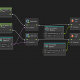
Overview of the Rapid Tapping Game
The game challenges you to see how many times you can click a button within 10 seconds.

FIN
Installing a Package in Unity
Please download the sample with only the UI layout done.
https://github.com/Manufuki/ClickGameUISample.git
Click the green “Code” button and select Download ZIP. Extract the downloaded ZIP file.
If you get stuck,
download the example created by the author.
https://github.com/Manufuki/ClickGame.git

Github
Click Asset→Import Package→Custom Package.

Asset→Import Package→Custom Package
Select ClickGameUpdate and click “Open”.

ClickGameUpdate→Open
Click Import.

Import
Click Import TMP Essentials.

Import TMP Essentials
It may not be displayed depending on your environment, but there is no problem.
Button Input with Visual Scripting
Open the “ClickGameSample” scene from the imported package.
Add a GameObject to the Hierarchy by clicking CreateEmpty, and rename it to [GameController].
Attach a Script Machine to [GameController] from AddComponent.

GameController→Script Machine
Click New on the Script Machine to create a graph.
Create a folder named Macros, and save it as [GameManager] within that folder.

Macros→GameManager
Add On Pointer Click to the GraphEditor.

On Pointer Click
Add a GameObject type variable to Variables.
Name the variable [Button] and set the Value to the Button in the Canvas.

Add GameObject Variables
Drag and drop the Button into the GraphEditor and connect the nodes as shown below. This completes the button functionality.
By connecting the object that acts as the button to the left port of On Pointer Click, you can make it execute when that object is clicked.

Connect nodes
Calculations with Visual Scripting
Next, we will perform score and time calculations for the rapid tapping game.
The basic calculation nodes are as follows:

Main nodes
This time, we will use the Add node. There are different types of Add, and the variables to be used are in parentheses.
Since Generic supports all variables, it is generally recommended to choose the Add node labeled Generic.
The same applies to other calculation nodes.

Generic
Add Int type and Float type variables to Variables.
Name the Int type variable [Score] and set the Value to 0.
Name the Float type variable [Time] and set the Value to 10.

Add variables
Add the [Time] and [Score] variables to the Graph Editor.
Score Function
Let’s start by creating the Score function.
Add an Integer Literal.

Integer Literal
Enter 1 into the variable.

1
Add a Set Object Variable.

Set Object Variable
By using Set Variable, you can assign a value to a variable. Set the variable part to Score in the second port from the top.
Connect the object storing the variable to the next port down, and connect the value to be assigned to the bottom port.

Score
The node should look like this:

Connect nodes
Time Limit
Next, let’s add the time limit feature.
Add Subtract, Get Delta Time, and If nodes to the Graph Editor.

Subtract
Get Delta Time can retrieve the time between the previous frame and the current frame.

Get Delta Time

If
Add a Set Object Variable. Set the variable to be assigned to Time.
Then connect the nodes as shown below.

Connect nodes
Run the program and focus on the Variables.
When you click the button, the Score variable will increase by 1 each time.
The Time variable decreases in accordance with the passage of time.

Play scene
This time, we covered score calculation and time calculation.
In the next second part, we will learn about displaying text, using SetActive, and scene transitions.
You can check the second part of the article from the link below.
The post Introduction to Unity Visual Scripting Part 3: How to calculate time and score [Part 1 of the continuous hit game] first appeared on STYLY.
]]>The post STYLY Mobile App Event Posting Manual first appeared on STYLY.
]]>The event tab refers to the list page where event information is displayed when you open the STYLY mobile app.
You can post information about urban XR events using STYLY.

Event Tab Screen
By posting content on the event tab, you can increase event awareness among users, set up experience pathways, and support event attendance.
- Event Awareness for Users
- Users can recognize and understand event information.
- The percentage of users interested in visiting the event increases.
- New Experience Pathways
- You can launch scenes from the experience methods section within the event tab (scenes using location markers are not supported).
- In addition to QR code activation on-site, a low-cost experience pathway can be established.
- Event Attendance Support Features (Add to Map Apps, Calendar)
- Users can use support features when visiting events.
- They can check event details in advance and register the event in their calendar (Google Calendar) to avoid forgetting.
Elements of the Event Tab
You can post event information on the event tab list page.
Event Tab Screen
You can describe the details of the event overview.

Event Tab Overview Screen
You can provide pathways to the experience location and post scene URLs. Users can directly launch scenes from the event page.

Event Tab Experience Methods Screen
Flow for Requesting to Post on the Event Tab
Only STYLY Business/Enterprise users can post event information on the event tab.
To post, please enter the event information using the event tab input form. Content will be supported in both Japanese and English. If the smartphone’s language setting is other than Japanese, it will be displayed in English. Uploading images is required when entering information, so you will need to log in with a Google account.
The event tab will be posted as soon as possible according to the desired date and time entered, once it has been reviewed internally by STYLY. The status will automatically change to Upcoming → Ongoing → Ended, or Permanent, and the order will also be adjusted accordingly. Please note that after submitting the form, you may be contacted by our staff regarding the posting.
Points to Note
- Currently, scenes using location markers are not supported for activation from the event tab.
- Please note that after entering the event tab input form, the content will be reviewed internally at STYLY before posting (If the content does not align with STYLY’s intended use cases, it may not be posted).
- The event tab may have new features added sequentially. Any updates will be announced accordingly.
The post STYLY Mobile App Event Posting Manual first appeared on STYLY.
]]>The post Introduction to Unity Visual Scripting Part 2: How to display “Hello World” using If statements, key input, and coroutines first appeared on STYLY.
]]>This article is the second installment of the Introduction to Visual Scripting series. You can check the previous article from the link below.
This time, we will introduce the process of displaying “Hello World” using If statements, key inputs, and coroutines.
“Hello World” is a phrase displayed when programming for the first time.
How to use If statements
Right-click in the GraphEditor to add an If node.
An If statement allows you to branch processing based on whether the condition is met (True) or not (False).

GraphEditor→If
Select the HelloWorld GameObject and add a new Boolean (Bool type) variable in the Variables section of the Inspector.
(A Boolean variable represents True if a certain condition is met, and False otherwise.)
This time, we named it “HelloBool”. Drag and drop “HelloBool” into the GraphEditor.

HelloBool

HelloBool
Connect the nodes as shown below. You can right-click on the root of the connecting line to remove it.
The OnUpdate node executes the connected process every frame

Conect nodes

Conect nodes
The purple port of the If node connects to the Boolean condition. The right port connects to the process for when the condition is True.

If
Press the play button at the top to run the scene
The If statement is processed every frame, and the Debug.Log process is executed when the value of “HelloBool” is True
Since Debug.Log is connected to the True port of the If node, if you set the value of “HelloBool” to False, Debug.Log will stop. It will resume when set back to True.

Play scene
Displaying HelloWorld by pressing a key
There are two ways to implement key input: Input Get Button and Input Get Key.
First, let’s use Input Get Button.
This time we will use the A key.
Open Edit→Project Setting→Input Manager from the main menu bar.

Edit→Project Setting→Input Manager
Change the size to 19.

Size=19
The “Cancel” at the bottom will be duplicated, so set its Name to “A” and the Positive Button to “a”.

Name=「A」、Positive Button=「a」
Add a Get Button Down node to the Graph Editor.

Get Button Down
Supplement
Get Button Down: Becomes True when the key is pressed.
Get Button Up: Becomes True when the key is released.
Get Button: Becomes True while the key is being pressed.

Get Button~
Enter “A” in the Button Name.
Reconnect the previous nodes and connect them as shown below.

Button Name=A
Since Get Button Down becomes True when the key is pressed, connect it to the purple port.
Let’s run the scene. When you press the A key, HelloWorld is displayed in the Console.

Play scene
Next, let’s use Input Get Key.
Add Input Get Key Down.

Input get key Down
Select Space for the Key. Reconnect the nodes as shown below.

Key=Space
Run it. You can display HelloWorld by pressing the Space key.

Key=Space
The difference between them is that GetButton allows the user to change the input key on the application side.
This is because the key specification method is a string type, so if the variable is set to a different string, it can perform the same process with different keys. On the other hand, GetKey cannot do this.
Therefore, when developing an application for production, use GetButton, and for debugging or programming practice, use GetKey.
Display HelloWorld using Coroutines
A coroutine is a program that executes a process after a certain amount of time has passed.
This time, we will use the following nodes.
|
WaitForSecond |
Waits for a few seconds (variable) |
|
WaitUntil |
Resumes when the condition is True |
|
WaitWhile |
Resumes when the condition is False |
Let’s add each node.

Add nodes
We will start with WaitForSecond.
To use a coroutine, you need to check the Coroutine box in OnUpdate.

OnUpdate→Coroutine
HelloWorld will be displayed 3 seconds after pressing the Space key. Enter “3” in the Delay. Connect the nodes as shown below.

Delay=3
Run it. HelloWorld was displayed in the Console 3 seconds after pressing the Space key.

Play scene
Next, we will use WaitWhile and WaitUntil.
Add a string variable from Variables. Name it “GoodByeWorldString” and set the value to “GoodByeWorld”.
Drag and drop “HelloBool” and “GoodByeWorldString” from Variables into the GraphEditor.

WaitWhile&WaitUntil
Add OnUpdate and Debug.Log to the GraphEditor and connect the nodes as shown below.

OnUpdate&Debug.Log
Run it. When HelloBool is False, WaitWhile resumes, and HelloWorld is displayed.
When HelloBool is True, WaitUntil resumes, and GoodByeWorld is displayed.

Play scene
Good job! This concludes the second installment.
Next time, we will introduce how to install Unity packages, button input, and calculations through the creation of a rapid tapping game.
The post Introduction to Unity Visual Scripting Part 2: How to display “Hello World” using If statements, key input, and coroutines first appeared on STYLY.
]]>The post Introduction to Unity Visual Scripting: Learn the basics of connecting nodes first appeared on STYLY.
]]>


The post Introduction to Unity Visual Scripting: Learn the basics of connecting nodes first appeared on STYLY.
]]>The post [AI] Generate high quality 3D models with Meshy first appeared on STYLY.
]]>Meshy
Meshy is an AI tool that can perform text input, 3D model generation from images, and texturing.
Features
Text to 3D : Easily create 3D models from natural language prompts in multiple languages including English, Japanese, Korean, Chinese, German, etc. You can also extract prompts from your own images.
Image to 3D : Generate 3D models from your own images.
AI Texturing : Textures can be added to your own 3D models using the prompts.
User Friendly : The tutorial provides tips and tricks for creating beautiful models and effective prompts, so that even first-time users can smoothly proceed through the process.
How to Use
First, access Meshy and click “Start for Free” in the upper right corner of the screen to register your e-mail address and create an account.

Start for Free

Enter your email address
.
When you move to the home screen, you will see that you own 275 credits in the upper right corner of the screen.
These credits are consumed when doing things like generating models, and free users can earn 200 credits per month.

credits
Now let’s touch on Text to 3D.
Click on Text to 3D in the AI Toolkit to start the tutorial.

Click on Text to 3D
.
Follow the instructions for this tutorial.

Follow the tutorial as instructed

Proceed with the tutorial as instructed

Proceed with the tutorial as instructed

Proceed with the tutorial as instructed
.
After the tutorial, you will be able to enter your own prompts.
Entering Prompts
In Meshy, you can enter all the prompts yourself, or you can create your own prompts from images or from prompts used by other users.
Let’s start by entering a prompt in the usual way.
If you are familiar with AI generation tools, you can create your own prompts, but if you are unfamiliar with them, you can try combining the prompts provided.

prompts prepared
I am going to create a stone statue of Cthulhu around the cthulhu prompt that was provided.
I entered “cthulhu, full detail sculpted totem, 8k texture, 4k details, realism , artstation trending, super detail” for the Prompt and “Ugly, Blurry, Messy, Deformed, Inconsistent, Bad Anatomy,Low Quality” for the Negative Prompt.

Enter Prompt
.
Negative Prompt is to add elements that you do not want included in the generated results.
After entering the prompt, click Generate.
Wait a moment and the mesh will be generated.
The generated one is of low quality as it is, so we will Refine it (20credit consumed).

Refine
When the Refine is complete, you will see that the quality has improved considerably.
When you are satisfied with the quality, click Download to download the model and textures.

Download
You can choose from fbx,obj,glb,usdz,stl,blend as downloadable formats.
When you check the download, you will find that the model data and various textures are stored.

model and various textures
.
If you cannot open the downloaded fbx or obj in Blender or other programs, move the file to the desktop and rename it appropriately so it will load correctly.
We were able to generate a high quality model using a total of 25Credit for generating and refining the model.
Extracting Prompts from Images
Click on the image icon on the Prompt tab and drag and drop your own image, this time a transparent image of my cat.

My cat
After uploading the image, click Generate Prompt to generate the prompt.

Generate Prompt
Wait a moment and the prompt will be generated, then click on Send to Prompt to send the prompt.

Send to Prompt
Set Art Style to Auto and click Generate.

Click Generate
.
Wait a moment and the mesh will be generated.

The mesh is generated
.
Art Style was set to Cartoon so it looks like a character.
If you use the Image to Prompt as is, it is not that accurate, so it is better to use it as a reference.
Using Prompts from Other Users
Meshy allows you to use high-quality prompts created by other users.
Click the magnifying glass icon on the prompt entry screen to see the details of models created by other users.

Click on the magnifying glass icon
.
In this case, we will use this Buddha image prompt.

Check the prompts of other users
.
Change the prompt slightly and click Generate.

Generate
Once the model is generated, Refine it.

Refine

Refined
A model of the Buddha statue has been generated.
AI Texturing
Textures can be added to the prepared 3D model.

AI Texturing
Go to AI Texturing, click New Project, choose a title and add the 3D model you have prepared. fbx, obj, glb, gltf, stl formats can be used.

Click on New Project
.
This time we will add a texture to the sofa model.
After adding the model, click Create Project.

Create Project
Once added, add the name of the thing to Object, enter the prompt and click Generate.

Click Generate
.
Wait a moment and the texture is generated.

Texture generated
.
The generated texture can be downloaded by clicking Download on the right side of the screen.
Other Information
Meshy is compatible with Unity and Blender, and plug-ins are available to use Meshy on each of these software packages.
Please check Meshy’s website for detailed tutorials and other information if you are interested.
Upload to STYLY
Upload your scene to STYLY and use it.
In this case, we will upload the Unity scene to STYLY as it is.
How to create an account
The post [AI] Generate high quality 3D models with Meshy first appeared on STYLY.
]]>